Apr 20, 2013

Homemade Huawei BM622 LAN LED Programmer Flasher

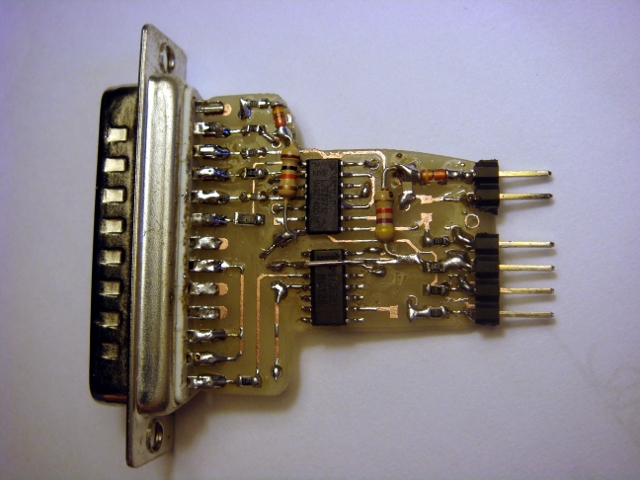
This Homemade Huawei Echolife BM622 4G WiMAX CPE broadband wireless modem router LAN LED programmer flasher is a DIY using LPT printer port on old legacy PC, beware of using USB to LPT it will not work.


The hardware schematic diagram is wide available on the net, likewise part can be also purchased at local store. You can download the Willem programmers  its free, Programmer is very cost effective and suitable for electronic applications (PC BIOS, satellite receivers, DVD update/repair and more...).

Latest HW version EZoFlash4v5

EZoFlash+ 4v4

Schematic Diagram :


Programmer EZoFlash support :
  • 8bit , 8/16bit and 16 bit flash memory in TSOP, PSOP, DIP and PLCC packages,
  • EPROM, E(E)PROM and E2PROM parallel memory, FWH/LPC and AT89C51 family,
  • +3.3V and +5.0V Vcc devices,
  • address range to 64Mbit (..A22),
  • +12V driver for programming and temporary sector unprotection,
  • adapters with standard sockets for DIP and PLCC devices,
  • adapters with memory chip soldering or surface mount identical footprint sockets (Meritec, Yamaichi) for TSOP , PSOP and SSOP devices,
  • software commands - get ID, read, verify, erase, blank check and program.
  • Latest version EZoFlash4v5 support serial EEPROM (I2C, Microwire, SPI), SPI Flash, Microchip PIC, Atmel AVR-8bit MCU (ATmega, ATtiny, AT90)
EZoFlash+ installation guide.


1.) Power supply output voltage +15…+18V, max current 300mA or more. Be sure , power supply connector internal positiv ! Recommended power supply with stabilised output voltage.
Check filtered non-stabilised power supply output voltage drop, load shortly power supply connector with resistor about 150 Ohm (load 100-120mA). Output voltage schould remain in recommended voltage range. Expect EPROM adapters use, check power supply voltage with resistor about 47 Ohm (load 300-350mA).
DC Power Jack and Plug are available with internal pin diameter 2.1mm or 2.5mm. Adapt both connectors for the same size.
Be sure on power supply isolated output voltage, no static voltage between power supply connector and computer grounds.

2.) Programmer EZoFlash+ default jumpers are Jp1, Jp3, Jp5.
Programmer logic IC and target chip have +5V voltage, A18 used on connector BU3.
Change jumper Jp5 (A18) to Jp4 (RST/Vpp) for BU3 based adapters only where Vpp or RST required , read settings in adapters page.
Change jumpers Jp1, Jp3 (+5V) to Jp2 (programmer +4.3V, target chip +3.6V) for low voltage (2.7-3.6V) target memory chip.
Change jumpers Jp1, Jp3 (+5V) to Jp2, Jp3 (+4.3V) for FWH/LPC adapters.
Other voltage options are available, for example all jumpers Jp1..Jp3 removed – programmer +3.6V, target chip +2.95V.

3.) Required adapter for target chip find in EZoFlash adapters page. Details and settings find on selected adapter page.
Corresponding flash memory and FWH/LPC chip adapter can be found in chip database.
Common jumpers on adapters – Jp7 (Vpp=Vcc), Jp8 (Vpp=+12V)
Extra adapter – voltage converter dc2dc_a4 is used with EPROM adapters to have higher programming voltages (Vcc=+5.7V , +6.2V ; Vpp= +12.5V…+13.2V, +21V, +25V)
Crossadapter prot_a1 is used for 8-bit flash memory adapters to provide sector lock/unlock in high voltage autoselect mode.
Verified chips, used adapters and test results are summarized in chip_test file.

4.) EZoFlash+ programmer works with Willem group programmer software in main PC OS , Windows XP and Windows 98SE preferably. Recommended latest software version 0.97ja. Sometimes useful are old versions 0.97g and 0.94a .
Software versions 0.98b, 0.98c, 0.98dx (0.98d2,.. 0.98d5) are not EZoFlash+ compatible.
Have a file setup97ja.exe, run it and follow to guide. Directory EPROM3 with files EpromM51.exe and io.dll will be created in Program Files. Uninstall option , Shortcuts in Desktop and Programs Menu are available.
Have a package with files EpromM51.exe (10.06.2004, 0.97ja ) and io.dll, unzip it and place both files in the same directory.
Have a package with files EpromM51.exe (26.01.2003, 0.97g or 21.02.2004, 0.94a) , dlportio.sys, dlportio.dll , unzip it and place all files in the same directory.
Click on program icon or it shortcut, programmer software window is launched.

5.) Utility 29C0x0.exe read boot block lockout on Atmel and Winbond small sector flash memory. Winbond chips boot block lockout can be enabled/disabled.
Utility hvasm.exe allow 8 bit flash memory sector lock/unlock in high voltage autoselect mode.

6.) Printer LPT extension cable is used to connect programmer and PC. Cable has 2 connectors (male and female), wired 1:1 according pin numbers. Shorter cable is recommended, but no more than 1.8m. Cable wires should be shielded , shield connected to both connectors housing. Long cable, bad quality and without shield may cause random errors in data transfer.

7.) Willem software supports programmer connected to standard LPT1, LPT2 or LPT3 port. Set selected in programmer software, settings “Printer Port”
Laptops with parallel port converters, PC with specific LPT port adress are not supported.
Recommended install registry XP_stop_polling.reg on PC with Windows XP. It stops PC internal resources random access/scan to LPT port. Check and close active resident programs that can use parallel port.
Generally data transfer works on default LPT port settings. Check parallel port settings in PC BIOS, sometimes change from ECP mode to EPP or Normal required.
Utilities are LPT1 supported only.

8.) Installing sequence.
  • Connect LPT cable to PC and programmer.
  • Run Willem software.
  • Connect power supply to programmer. Programmer green LED flash only.
  • Run Willem SW command Help/Test Hardware. Expect reply “Hardware present”
  • Insert adapter with target memory chip.
  • Run Read/Erase/Blank check/Program.
  • Command in progress – red LED flash (Vcc on), yellow LED flash (Vpp on).
  • Command finished, programmer green LED flash only. Remove adapter or replace target memory chip.
9.) Powered programmer - don’t connect and disconnect LPT cable.
Software not launched - don’t use or install adapter with target memory chip. All LED’s can flash on powered and connected programmer without software, target chip can be damaged !!
Command in progress, red or yellow LED flash - don’t remove or install adapter with target memory chip.

10.) Share your experience and problems in EZoFlash forum.

Chinese site exploits Apple's own tools to distribute pirated apps without jailbreaking

Chinese pirate site 7659.com is exploiting Apple's bulk enterprise licensing tools to distribute free versions of paid App Store applications. Bulk enterprise licensing is supposed to let businesses send in-house apps to employees without dealing with Apple's App Store. It works via a developer provisioning profile, which facilitates "sideloading" of sorts without jailbreaking.


The site is only open to users in China, but that restriction can be circumvented via proxy server. According to VentureBeat, 7659 is full of apps that would otherwise cost money. Those include our best new app last week, Badland, which is usually $3.99, and Final Fantasy V, priced at $15.99 in the App Store. In a statement on its site, Kuaiyong, the company that appears to run 7659, explains its reasoning behind offering the apps:
"First of all, we would like to thank all Apple users around the world and your support for Kuaiyong.

Statistics have shown that a significant amount of Apple users are Chinese based. However, the fact is that in China, a large number of Apple users are not very familiar with the iTunes system and how to effectively manage it.

In order for Chinese Apple fans to download applications securely, Kuaiyong developed its own method of giving users access to thousands of free apps without having to jailbreak their devices. Kuaiyong offers detailed descriptions of apps, free app download trial, IOS device management and visual and audio file backup system. IOS system backup and recovery features will also be released in the very near future.

Our goal has always been about bringing Chinese Apple users with quick, convenient and pleasant IOS experience. Since the introduce of Kuaiyong, the proportion of jailbreak in China has declined dramatically from 60% to around 30%. Kuaiyong will hold on to this goal in the future and we would like to see more support for Apple as well as Kuaiyong."
Kuaiyong's justification for providing pirate apps — that navigating the App Store is difficult for Chinese users — is laughable at best. It would appear that Apple won't have a particularly tough time putting a stop to this, though, as all of the apps are provisioned with the same developer profile. Apple just needs to find a way to cut 7659's profile off. Of course, there's always the chance that the same organization could use another developing profile to achieve the same thing, and it's not clear if Apple is able to remove apps remotely from users' phones. VentureBeat says it asked Apple for comment on the matter "multiple times" without response, but we've also reached out to ask how it plans to deal with 7659.com. - source

The Solar Cell That Turns 1 Photon into 2 Electrons

MIT researchers develop an organic solar cell that breaks 100 percent quantum efficiency

Solar cells are picky. If an incoming photon has too little energy, the cell won’t absorb it. If a photon has too much, the excess is wasted as heat. No matter what, a silicon solar cell can never generate more than one electron from a single photon. Such harsh quantum realities severely limit the conversion efficiency of photovoltaic cells, and scientists have spent decades looking for work-arounds.


Now, researchers at the Massachusetts Institute of Technology’s Center for Excitonics have published a compelling case that the key to greater solar efficiency might be an organic dye called pentacene. In today’s issue of Science Daniel Congreve, Jiye Lee, Nicholas Thompson, Marc Baldo and six others show that a photovoltaic cell based on pentacene can generate two electrons from a single photon—more electricity from the same amount of sun. Scientists have suspected for some time that this might work; today’s paper is proof of concept.

The key is a phenomenon called singlet-exciton fission, in which an arriving photon generates two “excitons” (excited states) that can be made to yield two electrons. Previous researchers had accomplished similar tricks using quantum dots (tiny pieces of matter that behave like atoms) and deep-ultraviolet light. “What we showed here,” Baldo says, in addition to using visible light, “is that [this process] works very, very effectively in organic materials.”

Why it works is still not particularly clear, and for now, the pentacene cell works only with an extremely narrow band of visible light. But Baldo says it should be possible to create a pentacene coating for silicon solar cells that boosts the total conversion efficiency from today’s 25 percent to a shade over 30 percent—a significant jump. Developing that technology is the obvious next step. “Can we apply this thing as a coating on silicon?” Baldo says. “If we can do that, it would have a pretty major impact on solar cell technology.” - source

Most Awaited Driverless cars expected by 2025

Google has been testing a fleet of autonomous vehicles on U.S. roadways for quite some time now, and other companies such as Mercedes-Benz are adding more advanced technology to aid drivers. We now have cars that can automatically stop, parallel park themselves and even detect when another car is in a blind spot. Google executives have previously said that they would like to see self-driving vehicles on the road within three to five years, however it may not happen that quickly. Industry experts believe that by 2020, car computers will handle much of the work when traveling at high speeds and five years later, we could finally see fully autonomous vehicles arrive “in meaningful numbers.”


The dates given are still “guesstimates,” Christian Schumacher, head of advanced driver assistance systems in North America for Continental, told The Wall Street Journal. She also noted that there are many obstacles the industry must overcome to make driverless cars a reality. One concern is the question of liability: Who should take the blame if a self-driving car gets in an accident?

Then again, accidents may be so rare that it could be a non-issue. Google’s self-driving cars have logged more than 300,000 miles across a wide range of traffic conditions and have not caused a single accident. Automakers and regulators in the U.S. and Europe are serious about the future of autonomous or semi-autonomous vehicles and have been pushing the technology in an effort to improve safety.

NHTSA researcher W. Riley Garrott revealed some interesting data this week at the SAE International World Congress in Detroit. According to the agency’s crash data, only 1% of drivers involved in a crash apply the brakes at full force prior to the impact, while 33% of drivers don’t apply the brakes at all. He said that accidents due to poor braking were found to cost society about $45 billion, based on data from 2006 to 2008, and that these new technologies would not only save lives, but also money.

As we patently wait for self-driving vehicles to arrive, Garrott noted that the NHTSA intends to make a decision by the end of the year on whether technologies such as “crash imminent braking” should be a standard across the automotive industry. - source

Malicious DDoS Attack On Reddit Continues

Reddit is currently under a large DDoS attack, according to the official Twitter account. The main site is functioning well, but some features have been disabled throughout the attack to keep the website speed stable and servers running.


The attack is a denial of service attack, one of the most common by hackers and Anonymous groups. The basic understanding on denial of service is thousands/millions of requests being sent at a time, making the servers shut down.

Most of the DDoS programs come free and can be installed and utilised quite easily, this is why it is such a common attack. The problem is you need a lot of bandwidth to make problems occur on the website.


The attack seems to have started on Friday, around the time the Boston Marathon bombings happened. Reddit users have been working to try and find potential suspects to help with the FBI investigation.

One of Reddit’s admins stated the attack was from someone with “a lot of time and bandwidth on their hands.” This would not be the first attempt at taking down Reddit, with many attacks happening to try and shut down the servers.

Reddit has said this is the biggest DDoS attempt on this scale ever, however Reddit is one of the most viewed websites and should be able to withstand this attack.

We are unsure what the course of action is, apart from finding IP addresses and loop holes in the attack and making sure the servers don’t go down. If they do, backup servers need to be prepared.

Android Malware Can Launch DDoS Attacks From Your Smartphone

Be careful of what you install on your Android device as you might unwittingly get it infected with malware. A new Android malware has just been discovered called Android.DDoS.1.origin and works by carrying out a DDoS (Distributed Denial of Service) attack from your smartphone to any target.


This latest threat was discovered by a Russian security company, Doctor Web, which reported this new threat uses social engineering techniques to spread itself. Android.DDoS.1.origin disguises itself as a Google Play icon tricking users into thinking it is the real thing. Once you click on it you will be routed to the actual Google Play store which is its way of distracting you from what is really happening.

This malware works in the background without your knowledge. Once it is activated it searches for its command and control center and sends out information regarding your device there. One piece of information that will be sent is your phone number. The criminals will be using this number to send text messages to your phone to control the malware.

The commands that can be sent to your infected device are for it to launch a DDoS attack or to send out text messages. A DDoS attack is performed when your device receives an IP address and a port that that it will need to ping. While one smartphone won’t make a difference, imagine what millions of infected smartphones can do to a particular site. It’s going to take that site down once it reaches critical mass. Your device can also be used as a platform to send spam text messages which might let you incur charges from your network provider.

The good news about this is that it doesn’t seem to be spreading quickly. You should however be prepared to take preventive measures by always making sure to have an updated security software running on your Android device. - source

Budget iPhone rear plastic shell?

Earlier this week, case manufacturer Tactus was one of several sources to share photos of cases reportedly designed for the fifth-generation iPad, once again showing that the device is expected to be smaller than the existing iPad and take design cues from the iPad mini.


Today, the company shares a photo of what is said to be the rear shell of Apple's rumored lower-cost iPhone. In line with previous rumors, the part appears to be manufactured from plastic.

The part is also consistent with iLounge's January description of the device, carrying a design somewhat similar to the iPod classic with a flat back and curved edges, as well as a shift to elongated volume buttons along the left side.

The report also shares a number of other claimed details about the device, including word of an A5 chip, a 5-megapixel rear camera, and five color options of black, white, blue, red, and yellow. The device is also claimed to carry a 3.5-inch Retina display rather than the 4-inch display seen in the iPhone 5, although that detail conflicts with reliable analyst Ming-Chi Kuo's claims of a 4-inch display for the lower-cost iPhone.

Finally, Tactus claims that the lower-cost iPhone will launch on October 15 and be priced at $300, although we place little faith in those details given that any source for part leaks likely coming through Apple's supply chain or accessory manufacturers would not be aware of Apple's specific launch plans. The report also claims that the rear shell is 0.4-0.6 mm thick, which is obviously not an accurate measurement and is likely a misreporting of previous claims that it would be 0.4-0.6 mm thicker than the iPhone 5.

We also can not verify whether this is indeed a legitimate rear shell for Apple's lower-cost iPhone. It could simply be manufactured based on circulating rumors, but even if fake it could be an accurate representation if it is based on design specs leaking through case makers. Case makers have a number of times created accurate physical mockups of Apple's upcoming devices, although they have on occasion been incorrect.

Huawei Echolife BM622 JTAG Serial Pinout

Today I have found the easy, best and simple way on How-To repair the Huawei Echolife 4G WiMAX CPE broadband wireless modem router being so-called firmware destroyer or FWD most of the times it is also referred as "bricked". On the other hand, Blank WAN is totally different you can navigate to the graphical user interface (gui) except your WAN intferface MAC address is BLANK and therefore techie labeled it as "blank WAN" this also can happen to the CPE. With this recent release of JTAG and Serial pinout there would be no more "Baklas Kabit" DIY hopefully.


The JTAG pinout must be tested first not with analog or digital multimeter because it will not do the work, eGizmo PIC18F2550 Pinguino is Andruino clone board can do the task on Boundary Scanning for absolute reading with open source apps.

Apr 19, 2013

eGizmo PIC18F2550 Pinguino – Arduino like Board

eGizmo PIC18F2550 Pinguino board is based on Arduino platform pin layout. Instead of using the Atmel AVR microcontroller, Pinguino uses Microchip PIC18F2550.


Features
  • gizduino/arduino pin compatible
  • gizduino/arduino shields compatible
  • ICSP header for programming with e-Pickit2/pickit2
  • PL2303 usb to uart chip for uart debugging
More on Pinguino is discussed on Hacking Lab.

The e-Gizmo Pinguino board is pin compatible with Arduino shields and users has the option to program the PIC18F2550 with Pinguino IDE or any microchip compatible compiler and programmer like the e-Pickit2.

Source: PIC18F2500 Pinguino Compatible e-PICKIT2

TP-Link WR703N Debrick with Arduino UNO

I recently flashed OpenWrt on a TP-Link WR703N and got locked out (Ethernet was not working and WiFi is disabled by default). I soldered the wires to get serial access, but I did not want to purchase a USB serial adapter (could have, but decided not to). I wanted to see if I could use an Arduino UNO I had laying around to debrick my device, so I came up with this small sketch.


/*
Arduino OpenWRT Serial Debrick Sketch
Piero Toffanin - 2013

Usage:
Power off the TP-Link
Connect TP_OUT --> Arduino RX Pin
Connect TP_IN --> Arduino TX Pin
(Optional) Connect 1000 Ohm resistor in series with an Led --> Pin 13
Setup TFTP server with IP 192.168.1.100/24
Place your image in the root TFTP folder and rename it "openwrt.bin"
Connect Ethernet cable from TP-Link to TFTP server
Upload Sketch to Arduino
Power up the TP-Link
LED will turn on during the de-bricking process
Wait ~1 minute
LED will flash 10 times when process is over
Remove connections
Reboot the TP-Link by turning it off and on
Buy me a beer

MIT License
Copyright © 2013

Permission is hereby granted, free of charge, to any person obtaining a copy
of this software and associated documentation files (the “Software”), to deal
in the Software without restriction, including without limitation the rights
to use, copy, modify, merge, publish, distribute, sublicense, and/or sell
copies of the Software, and to permit persons to whom the Software is
furnished to do so, subject to the following conditions:

The above copyright notice and this permission notice shall be included in
all copies or substantial portions of the Software.

THE SOFTWARE IS PROVIDED “AS IS”, WITHOUT WARRANTY OF ANY KIND, EXPRESS OR
IMPLIED, INCLUDING BUT NOT LIMITED TO THE WARRANTIES OF MERCHANTABILITY,
FITNESS FOR A PARTICULAR PURPOSE AND NONINFRINGEMENT. IN NO EVENT SHALL THE
AUTHORS OR COPYRIGHT HOLDERS BE LIABLE FOR ANY CLAIM, DAMAGES OR OTHER
LIABILITY, WHETHER IN AN ACTION OF CONTRACT, TORT OR OTHERWISE, ARISING FROM,
OUT OF OR IN CONNECTION WITH THE SOFTWARE OR THE USE OR OTHER DEALINGS IN
THE SOFTWARE.
*/


#define BUFZSIZE 800
#define DEBUGPIN 13 // Connect a resistor + LED to this pin to see debug activity

char buffer[BUFZSIZE];
int c;
boolean tpl;
int command;
boolean done;
void setup()
{
pinMode(DEBUGPIN, OUTPUT);
digitalWrite(DEBUGPIN, LOW);

Serial.begin(115200);
int i;
for (int i = 0; i < BUFZSIZE; i++) buffer[i] = 0; tpl = false; done = false; command = 0; } void loop() // run over and over { start: if (!done && Serial.available() > 0){
char ch = Serial.read();
if (ch == '#') goto start;
buffer[c] = ch;
if (!tpl && c >= 6 &&
buffer[c] == 's' &&
buffer[c-1] == 'd' &&
buffer[c-2] == 'n' &&
buffer[c-3] == 'o' &&
buffer[c-4] == 'c' &&
buffer[c-5] == 'e' &&
buffer[c-6] == 's'){
digitalWrite(DEBUGPIN, HIGH);
delay(400);
Serial.print("tpl\n");
digitalWrite(DEBUGPIN, LOW);
tpl = true;
c = 0;
}else if (tpl){
if (c >= 6 &&
buffer[c] == '>' &&
buffer[c-1] == 't' &&
buffer[c-2] == 'e' &&
buffer[c-3] == 'n' &&
buffer[c-4] == 'r' &&
buffer[c-5] == 'o' &&
buffer[c-6] == 'h'){
digitalWrite(DEBUGPIN, HIGH);
delay(8000);
if (command == 0){
Serial.print("setenv ipaddr 192.168.1.101\n");
}else if (command == 1){
Serial.print("setenv serverip 192.168.1.100\n");
}else if (command == 2){
Serial.print("tftpboot 0x81000000 openwrt.bin\n");
}else if (command == 3){
Serial.print("erase 0x9f020000 +0x3c0000\n");
}else if (command == 4){
Serial.print("cp.b 0x81000000 0x9f020000 0x3c0000\n");
}else if (command == 5){

//Serial.print("boot.m 9f020000\n");
//Serial.print("reset\n");

done = true;
int j;
for (j = 0; j < 10; j++){ digitalWrite(DEBUGPIN, LOW); delay(500); digitalWrite(DEBUGPIN, HIGH); delay(500); } digitalWrite(DEBUGPIN, LOW); /* Uncomment to print out buffer at the end (useful for debugging) for (j = 0; j < BUFZSIZE; j++){ Serial.print(buffer[j]); } */ // Stop while(true){ delay(100); } } command++; } } if (c++ > BUFZSIZE) c = 0;
}
}
The wiring is trivial and although Arduino's logic levels are different than the TP-Link it seems to work quite nicely. It basically waits for the proper U-boot message, sends the "tpl" command to enter the console and then sends the recovery commands. - source

RG100A Serial Position Wiggler JTAG Connection

I mentioned earlier in this article Nanjing Telecom donated Shanghai Bell Alcatel RG100A ADSL modem, did not expect the students glascholar from the Internet to buy a, I use violence to take it over first amend one.

Buffer 5V as shown capacitance bit access.


The Flash 16M, the above command only dump the 4M.
2 CPU arrow in the switch chip.

[Serial]
The first serial port. As shown in Figure 4-pin serial total of the order of 3.3 GND Tx Rx Unfortunately, the hole distance non-standard, so [tc] with a 4-pin cable cut bad GND to simulate non-standard hole spacing. Real GND cited elsewhere.

[JTAG]
Although individuals unbuffered JTAG structures, leading online most people are using this mode of four resistors to program the program, but I'm too lazy to find four 100 ohm, so it is still in use Wiggler JTAG done before ( here ).

Of course, hard to say how much help buffer for improving the signal strength. However, because the first 12 feet is compatible, so it is not difficult to work.

[Programming]
Screenshot after the connection is as follows (in part), where fc: 20 is said AM29LV320T compatible.
brjtag.exe-backup: custom / wiggler / window: 1E000000 / start: 1E000000 / length: 400000 / fc: 20 / silent


CPU Chip ID: 00000110001101011000000101111111 (0635817F)
*** Found a Broadcom BCM6358 Rev 1 CPU chip ***

- EJTAG IMPCODE .......: 00000000100000011000100100000100 (00818904)
- EJTAG Version .......: 1 or 2.0
- EJTAG DMA Support ...: Yes
- EJTAG Implementation flags: R4k MIPS16 MIPS32

Issuing Processor / Peripheral Reset ... Done
Enabling Memory Writes ... Done
Halting Processor ... ... Done
Clearing Watchdog ... Done
Manual Flash Selection ... Done
Flash Vendor ID: 00000000000000000000000000000001 (00000001)
Flash Device ID: 00000000000000000010001000000001 (00002201)
*** Manually Selected a AMD 29lv320MT 2Mx16 TopB (4MB) Flash Chip ***
- Flash Chip Window Start ....: 1e000000
- Flash Chip Window Length ...: 00400000
- Selected Area Start ........: 1e000000
- Selected Area Length .......: 00400000
bytes written: 4194304
=========================
Backup Routine Complete
=========================
elapsed time: 946 seconds
*** REQUESTED OPERATION IS COMPLETE ***
[Debug]
Detailed debugging I have not done, the next few days, in addition to the school thing, intends to compile several programs look on this machine. So stay tuned!

Netgear RP614 Router JTAG Serial

RP614 is a very cheap 4-Port DSL/Cable router from NetGear.

I bought this router from FutureShop and it was 29$ after rebate.

What is inside the box?

Since it's pretty cheap, I just wonder what is inside this little beast. So I unscrewed the router cover and revealed the secret.


As you can see from the picture, RP614 is mainly powered by the Samsung S3C4510B processor.


The memory devices are 1MB Flash(MX,16bit port) and 8MB of SDRAM(EtronTech, 16bit port).


There is a Broadcom 6 Port switch chip (the one with the heatsink) to do the 4 port ethernet switching job and connects to the S3C4510B's ethernet MII interface.

For the WAN interface which is supposed to be connected to the DSL/Cable modem, a ISA ethernet controller RTL8019AS from RealTek has been used on this router.


JTAG and Serial port

Fortunately, the NetGear designers left the Jtag and the serial port on the PCB. They are basically on the side near the Broadcom switch. They came with no connector soldered. So I have to solder the connecters by myself.


The JTAG is a standard 14PIN ARM JTAG debug port. It's compatible with the standard WIGGLER JTAG interface cable which could be easily found in the store or just make your own.

The serial port is a 10-pin connection but really you only need 3 pins out of it. Pin 3,4,10 are TXD, RXD and GND. But for sure you need a level shifter to be connected to your PC's RS-232 port. - source

Facts of Geothermal Energy

Asides from the Sun, the Earth's interior provides heat energy that can be effectively used for generating electricity. Yes, geothermal energy has been in existence since hundreds of years, however, extensive research has led to the possibility of tapping this renewable source of energy. The word geothermal is derived from two words, 'geo' and 'thermal'. Geo stands for 'Earth' and thermal is related to heat energy. So, geothermal energy is the energy that is generated inside the layers of the Earth's surface.

Generation

One of the most interesting geothermal energy facts is that it is generated deep within the Earth's surface. The Earth has three layers, the crust, the mantle and the inner core. Crust is the outermost part of the Earth's surface and it is this part that forms the continents and ocean floors. The thickness of this layer is usually between 3 to 5 miles under the oceans and between 15 to 35 miles on the continents. The mantle or the middle part surrounds the core and is nearly 1800 miles in thickness. Magma and rocks are the major constituents of this layer. The innermost layer or the inner core is divided into two cores, one is called the solid iron core and the other hot melted rock or magma. The Earth's crust is broken into a large number of pieces called plates. The hot melted rock or magma comes close to the edges of these plates and forms the volcanoes. The lava that comes out from a volcano is nothing but the magma. The deepest part of inner core contains magma at temperatures higher than the Sun's surface. The rocks and water found in the deep underground parts of the Earth's surface absorb heat from the magma. The temperature increases with an increase in the depth of the Earth's surface.

Where it is Found

Geothermal energy is hidden in the depths of the Earth's surface, however, it often finds its way out to the surface, in the form of volcanoes, geysers and hot water springs. Generally, the major sources of geothermal energy are the areas close to the major plate boundaries of volcanoes and earthquakes. The area, called a 'ring of fire', encircling the gigantic Pacific ocean is a very popular region for a lot of geothermal geysers and water springs. In the United States, geothermal reservoirs are found in the western states of Hawaii, Utah and Nevada etc. California holds the distinction for producing most electricity from geothermal energy. The US government has strict laws regarding the misuse of the lands in yellow stone national park where geysers and similar features are found.

More Information about Geothermal Energy
Some more interesting facts about geothermal energy are as follows.

  • Geologists test the presence of a geothermal reservoir, by drilling a well and recording the temperature deep beneath that place.
  • The entire resource of geothermal energy has been found to be more than that of coal, gas and uranium combined!
  • Iceland and Philippines produce 27% of the nation's electricity consumption by geothermal energy! They are the world leaders in geothermal energy production!
  • Sites where geothermal energy is tapped are called geothermal springs and in these places, water seeps into the Earth's surface and resurfaces as hot water!( the Earth's interior heats it!)
  • No fuel is consumed in producing geothermal electricity and the geothermal heating and cooling systems, so it is absolutely emission free.
  • The US government provides 'geothermal tax credit' that is a form of incentives to people saving electricity by installing geothermal heating and cooling systems
  • Geothermal plants emit 97% less acid content than fossil fuel plants!

Geothermal energy is considered to be a viable option for generation electricity, cooling and heating homes and is used in almost 20 countries of the world. Except for the high initial cost and space for installation, geothermal energy is an excellent alternative energy source.

Apr 15, 2013

Iloilo city sex scandal video: Teacher-student sex goes viral

A sex video of an alleged public high school teacher with a university student from Iloilo City went viral on social networking site Facebook but was removed after it sparked a wave of scorn among Internet users.


The video, assumed filmed in a boarding house, shows the two engaging in sexual activities, according to a Bombo Radyo report.

The woman, still wearing a university uniform was caught on camera having sex with the teacher while lying on a mattress spread on the floor.

The FB user who posted the video described the woman as a second year Accountancy student of a university while the man was in his 20s and teaches at a public high school in Iloilo City.

The 7-minute video appeared to have been posted on Facebook a few days ago. However, after it was broadcasted over different radio stations in the city, it spread like wildfire and had been shared more than 1,300 times and gained more than 2,000 likes.

However, the Iloilo sex video scandal was taken down by the Facebook user after the news hit the local media.

Meanwhile, the victims of the latest sex video scandal said that the source of their sex video could have been the cellphone which was allegedly lost few years ago.

The person who posted the video could be liable for violation of Republic Act No. 9995 or the "Anti-Photo and Video Voyeurism Act of 2009".

Under the said law, a person who posted the video could be penalized of imprisonment of not less than three years but not more than seven years and a fine of not less than P100,000 but not more than P500,000 or both. -Source: Bombo Radyo

Apr 14, 2013

Huawei BM622i MAC Change Package Date 2010

This is another How-To change the MAC address of Huawei Echolife BM622i 4G WiMAX CPE broadband modem wireless router firmware date package 2010. This tricks is a different approach as the previous post to Huawei BM622i MAC Change Package Date 2011. Although this is being done also thru CLI via telnet or putty client with specific command.


The above is a snapshot of Huawei Echolife BM622i 4G WiMAX CPE broadband modem wireless router date package 2010 firmware from Globe Telecom Philippines one of 4G ISP Telcos in the country.

To begin with click the Start button of your Windows machine make sure you enable your telnet client from your Conrol Panel>Promgram and Features because on 32/64bit Windows7 this is disable by default, Windows XP don't have the issue about it. Putty is an alternative if you want to be handy.

On Search Programs and Files type telnet 192.168.254.1 then press Enter

Or simply use putty


Telnet Command
Login: wimax
Password:wimax820
ATP>diag set macaddr 40:4D:8E:26:A1:7C

set Lan mac address success
Lan mac address updated 40:4D:8E:26:A1:7D
set Lan Mac address Sucess
Wan mac address updated 40:4D:8E:26:A1:7C

ATP>diag reboot
This must be the output of your telnet command line interface (cli) or putty screen.

The Huawei Echolife BM622i 4G WiMAX CPE broadband modem wireless router will then now reboot just wait for few seconds.

Open your fave browser on the address bar type http://192.168.254.1 login as admin account used any password generator with your MAC address you used in telnet cli as in my case I have used  40:4D:8E:26:A1:7C MAC address and yours might be differ.


Your WAN and LAN MAC addresses would  appear similar to the screenshot above, once you have login as admin you must be seeing this. To verify that everything will works, while logged in as admin account navigate the BM622i 4G WiMAX CPE interface on the left corner there is WiMAX Menu click Security Sub-menu we will confirm if the Profile Security Setting is in place such NAI, User ID and the User Password fail to do this even a valid MAC address will not let you connect to the ISP network.


If happen to you such as the screenshot above then you will be in trouble (this will keep on connecting only), as in my case I have used 40:4D:8E:26:A1:7C as my valid MAC address so will then input manually the NAI, User ID and the User Password just like the snapshot below.


Here the sample of NAI, User ID and User Password

NAI 404D8E26A17C@globelines.com.ph
User ID 2008t2EIHdNtQEMD

In my case once I set from telnet command line interface ATP>diag set macaddr 40:4D:8E:26:A1:7C it will automatically changed the NAI, User ID and the User Password.

Apr 13, 2013

Understanding JTAG

JTAG is a program for fixing your router if it is in an otherwise unrecoverable state. Jtag is done with a cable hooked from a computer 25 pin printer port (USB might also be available) to an electrical connection on your router called a jtag port. There are sometimes two similar ports on a router; one is the jtag port and the other is a serial port. These ports do not usually have the pins there to connect to, but are just holes in your router motherboard. You often need to solder a pin connector to your motherboard. This pin connector is called a header.


In order to understand jtag, you need to understand the three parts of the program that runs inside your router (known as the router's firmware). The firmware is composed of a bootloader, (that starts up the router's operating system), the NVRAM, (where information particular to your router are stored, like it's IP address and your ssid name) and the kernel which is the program that your router uses.

These three parts together are known as the WHOLEFLASH.

The bootloader on a DD-wrt is a linux bootloader, known as a CFE. Linksys also used a VXworks bootloader on some routers that has to be replaced with a CFE linux bootloader using a VXKiller program. So, when people talk about the CFE of the router, they are talking about the bootloader. Every router has it's own particular CFE. It has the MAC addresses embedded in it for your router, so each one is a little different. That is why it is so important not to ever delete this without backing it up. If you delete it, you at least have to find another one that is for your make and model of router. This can be tricky in some cases, so don't delete the bootloader!

The nvram is the place where variable information is stored. This is often where things get mucked up and is often the reason why people need to jtag their router. You can erase the nvram by doing a HARD reset of the router but sometimes the router will not respond. Then it is jtag time. If you delete the nvram, and have a proper CFE and kernel on the router, the nvram will rebuild itself. You don't need to jtag the nvram.

The kernel is the firmware. This is what you flash when you flash dd-wrt. DD-wrt IS the kernel. Again, if you have a CFE on the router, you don't need to flash the kernel with Jtag. If the CFE is working, you can flash using TFTP.exe or an equivalent program. Although you CAN flash the kernel using JTAG, it takes a LONG time and flashing using a jtag cable is not completely reliable, so you can end up with problems. You should not need to do this.

So if you have followed the bouncing ball, you should now understand that you should use JTAG primarily for two things:

1. Replacing a CFE

2. Erasing the NVRAM or kernel.

With that understanding, we can now turn to the brjtag program
Setting up the JTAG Program

To JTAG a router you can download a copy of hugebird's program from the SF.net files:

http://sourceforge.net/projects/brjtag/files/

You will note that there is a version 1.9, and a folder for a v.2.0. The 2.0 supports more router chipsets, but you have to rename it .exe from .bin.

You have to, on a Windows system, load giveio.sys. First you have to put it in the c:\windows\system32\drivers\ folder and then you have to load it using the loaddrv.exe program. Make sure you put the full path of the driver in the loaddrv.exe program as well as the file name. (c:\windows\system32\drivers\giveio.sys). Also note the giveio.sys driver needs to be installed only once. Subsequent needs for the driver during additional jtag sessions, or if your computer needs a re-boot, it only needs to be "started" by clicking on the "start" button of the loaddrv.exe driver loader utility.

Here are the steps:

1. Start your computer and unarchive the contents of 2.0.5 to your C:

2. Put giveio.sys in the proper directory: c:\windows\system32\drivers\

3. Start the loaddrv program and hit install. Make sure you add "giveio.sys" to the end of what appears in the window so it looks like this:

c:\windows\system32\drivers\giveio.sys [1]

4. Then hit start.

5. Then hit OK.

6. Remove the power supply from your router.

7. Hook up your jtag cable. Make sure you have pin one on pin one and the cable is not upside down on your router, and that you have the cable is hooked to your 25 pin parallel port

8. Plug your power supply into your router.

9. You might have to set the parallel port communications settings, but I have always found default settings work. If they don't please note that your rig needs to have a real printer port, not a usb to printer port adapter. The printer port should be set for ecp mode and standard io of 0x378.

Using JTAG

DO NOT POWER CYCLE WITH THE JTAG UTILITY RUNNING! If the jtag utility is running, do a control-C to stop it. IF YOU TURN THE POWER OFF WHEN THE JTAG IS RUNNING YOU MIGHT DAMAGE THE FLASH CHIP!

You should check to make sure your cable is working with a probeonly command:

brjtag -probeonly

If you don't get a response that recognizes your chipset, check your soldering carefully with a multimeter.

If you get a response that recognizes your chipset, the next command should always be to backup your CFE first, even if you think it is FUBAR. Better safe then sorry.

This is done with the command:

brjtag -backup:cfe

Do this twice and make sure the files match.

With most bricked routers, ALL you have to do is erase the nvram and the kernel. You do that with these commands:

brjtag -erase:nvram

brjtag -erase:kernel

DO NOT erase:nvram on a Belkin F5D7230-4 router. Doing so will erase important values and require you to have to jtag the kernel back on.

Doing that should put you back to a position where you can tftp the firmware back on. Stop and try that. You must disconnect your jtag cable to flash the firmware. Follow the guidelines for flashing by tftp found at note 11 of the peacock thread announcement, at the top of the broadcom forum.

http://www.dd-wrt.com/phpBB2/viewtopic.php?t=51486

DO NOT REPLACE THE CFE unless it is corrupt. A bad flash should NOT normally corrupt the CFE. However, if you have to replace the CFE, you must rename the CFE file CFE.bin, and then use this command

brjtag -flash:cfe

It is important to know, that if you do need to replace the CFE, an erase of wholeflash should be done prior to flashing the CFE.

brjtag -erase:wholeflash

The reason for this is if the kernel and nvram are left intact and only the CFE (bootloader) is replaced, when the bootloader boots the device, it will load the kernel. If a corrupt kernel or a bad nvram variable caused the bootloader damage in the first place, the offending pieces of the program are still present and may cause bootloader damage again as soon as the router is power cycled after the CFE flash.

If you need a CFE for a Broadcom router, you can find most through this link: http://www.dd-wrt.com/phpBB2/viewtopic.php?t=25971

However, these CFEs will contain generic Mac addresses, so you will likely have to hexedit your Mac address to the generic CFE prior to flashing.

JTAG on a Laptop Computer

Laptops don't normally have parallel ports anymore, and if your laptop doesn't you would be hooped. USB Jtag is expensive, and doesn't appear to work consistently well. The best option is to get a ExpressCard Parallel port adapter. Further information is in this thread:

http://www.dd-wrt.com/phpBB2/viewtopic.php?t=61256

Another simple programming FPGAs

In the last article I wrote , and that is the JTAG TAP controller. This knowledge will help us make a simple programmer for FPGA company Altera.

I want to make a very simple programmer that will work through the serial port. The serial port is good in that it is very common, easy to program and, in addition, there are low-cost devices USB-to-COM. The hope is that my programmer will work through this adapter. On the computer I'm going to run my special program that controls the programmer. We will write to her (in the sense I have already written and tell you how it works).

So, in the JTAG connector has 4 significant signal to us: TDI, TMS, TCK and TDO.
The first three signals are inputs to the programmable FPGA, so we have a computer to manage them. Each control signal to be random, any of them, we can at any time set or reset. We have several serial signals suitable for this purpose:
  • RTS - it will match the JTAG signal TDI
  • DTR - it will match the signal TMS
  • TX - would correspond to a signal TCK
In addition, the output signal has a JTAG TDO, the state of which we need to be able to read from the computer. We shall use for this purpose the CTS serial port.

With signals understood, but there is one problem. We need to do a level converter serial signals. Of course you can use a specialized chip level converters, of which there are a great many. For example, there is such a chip icon HIN202 (625.08 KB)

We are (as always) go our own way. We make the programmer's on the following scheme:


A few resistors, zener diodes, LEDs for debugging and .. that's it - simple as that.

Here are photos of our programming, top view:


View from below:


I will write a program in C language environment in Microsoft Visual Studio v10.

My program will consist of at least two logical parts. The first part - is the serial port control signals, which means it control signals JTAG. The second part of the program - it's reading *. SVF file, its interpretation and consistent performance. In the last article I wrote that the SVF file describes the sequence of commands for the TAP controller's programmable chip. Wednesday Altera Quartus II can generate SVF files to compile the project.

To control the serial port I use API functions OS Windows:
  1. CreateFile (..) - is used to open the serial port
  2. EscapeCommFunction (..) - the parameters SETRTS or CLRRTS to set or reset signal TDI
  3. EscapeCommFunction (..) - the parameters SETDTR or CLRDTR to set or reset signal TMS
  4. EscapeCommFunction (..) - the parameters SETBREAK or CLRBREAK to set or reset signal TCK
  5. GetCommModemStatus (..) - to read the state of the CTS line and thus learn the value of TDO signal from the JTAG interface
The program identifies two very important functions:
int sir (int nclk, int val);
int sdr (int nclk, int val);

The first function sir (..) writes to the command register TAP controller programmable chip val is a long nclk bit. The second function sdr (..) writes to the data register TAP controller programmable chip val is a long nclk bit.

Functions look about the same and do about the same thing. Using the TCK and TMS signals they carry TAP controller state record in the relevant register IR or DR according to the state diagram (TAP state-machine) described in the previous article. TDI signal is used for serial transmission of data on the register TAP, and the TDO signal is used to read response data from the controller.

Now for the interpreter SVF file.
So, you've done a project for the FPGA, compiled it using Quartus and got SVF file to program the chip.

SVF - a text file. Our program will read it line by line and interpret the command in this line and execute it. I do not know all the details of the standard SVF files, but what I see in the file generated kvartusom - this is a very simple file. One line - one team. There are no conditional or unconditional jumps or subroutines. Thus, reading and execution of SVF file line by line - it is a convenient solution for us.

Actually you need to implement only a few basic commands: RUNTEST, SIR, SDR. As you guessed team SIR - write down the number in the instruction register and the TAP SDR - write down the number in the data register. RUNTEST - a pause when the controller is in the state IDLE. I will say honestly that I pause in the program does not withstand strict. We've already gotten a very slow rate due to the recording software implementation protocol. So pauses according to SVF hope is not necessary.

Well, here's the program is written and compiled using Visual Studio.
You can download its source code and binary file on our website: Programming via the serial port (51.89 KB)

The program console, takes 2 parameters on the command line: the name of the serial port and the file name SVF. For example, like this:

c: \ MarsBlaster.exe COM4 my_proj.svf

Connect fee rover to our programmer, connect it to the computer has power.


It looks like it works!

To watch the video of this project from here

PS: fly in the ointment.
Via an adapter USB-to-COM works, but very slowly. Programming the Mars Exploration Rover (including verification after burning) takes about 5 minutes. The reason is that the control signal goes via USB and read the response signal TDO takes a very long time (2-3 milliseconds). Get rid of this so simply will not work. Need to do more complex programming, with more complex logic of that exchange would lead not one bit, but at least bytes, then you can do so much more quickly.

Well, a look at the programming scheme is "feedback" from the 6th to the 3rd leg connector COM port. This is the same need - just to work through the adapter USB-to-COM. This feedback allows you to accurately tell whether the data came on the status of TDO or not. I set the TCK and read through the feedback it well - he came or not. If you come, then came to him and TDO. A bit surprising happened, but it works. - source

MAX232 Serial level converter

When communicating with various micro processors one needs to convert the RS232 levels down to lower levels, typically 3.3 or 5.0 Volts.

Here is a cheap and simple way to do that.

Serial RS-232 (V.24) communication works with voltages -15V to +15V for high and low. On the other hand, TTL logic operates between 0V and +5V . Modern low power consumption logic operates in the range of 0V and +3.3V or even lower.

Thus the RS-232 signal levels are far too high TTL electronics, and the negative RS-232 voltage for high can’t be handled at all by computer logic. To receive serial data from an RS-232 interface the voltage has to be reduced. Also the low and high voltage level has to be inverted.

This level converter uses a Max232 and five capacitors. The max232 is quite cheap (less than 5 dollars) or if youre lucky you can get a free sample from Maxim.

The MAX232 from Maxim was the first IC which in one package contains the necessary drivers and receivers to adapt the RS-232 signal voltage levels to TTL logic. It became popular, because it just needs one voltage (+5V or +3.3V) and generates the necessary RS-232 voltage levels.

The requred parts:
  • 1 x max 232
  • 4 x 1uF capacitor
  • 1 x 10uF capacitor
  • Soldering iron, wires, breadboard etc.
Schematic


The MAX232 is an integrated circuit, first created by Maxim Integrated Products, that converts signals from an RS-232 serial port to signals suitable for use in TTL compatible digital logic circuits. The MAX232 is a dual driver/receiver and typically converts the RX, TX, CTS and RTS signals.


The drivers provide RS-232 voltage level outputs (approx. ± 7.5 V) from a single + 5 V supply via on-chip charge pumps and external capacitors. This makes it useful for implementing RS-232 in devices that otherwise do not need any voltages outside the 0 V to + 5 V range, as power supply design does not need to be made more complicated just for driving the RS-232 in this case.

The receivers reduce RS-232 inputs (which may be as high as ± 25 V), to standard 5 V TTL levels. These receivers have a typical threshold of 1.3 V, and a typical hysteresis of 0.5 V.

The later MAX232A is backwards compatible with the original MAX232 but may operate at higher baud rates and can use smaller external capacitors – 0.1 μF in place of the 1.0 μF capacitors used with the original device.

The newer MAX3232 is also backwards compatible, but operates at a broader voltage range, from 3 to 5.5 V.

Pin to pin compatible: ICL232, ST232, ADM232, HIN232 (much cheaper alternatives).

Homemade Xilinx Parallel Cable III

I needed a Xilinx JTAG cable for my CPLD project. I looked up the schematics for Xilinx Parallel Cable III, and found out I already had the two ICs that were needed. I was going to build another PCB for the project anyhow, so I decided to make this one as well.

I designed it using my trusted gEDA suite (xgsch2pcb = gschem + pcb). I made a one-sided PCB, since it’s much easier to manfacture at home.

Electronic sidenote: actually I had HC125 and HC126, not two HC125. But since the only difference between 125 and 126 is the OE inputs negation, and only 1/4 of the other HC125 is used, I only slighlty modified the schematic and finally it worked just fine.

I fired up IMPACT of the Xilinx WebPack, and it sort of worked, because it detected my xc9536xl CPLD, but refused to program it:

ERROR:iMPACT:583 - '1': The idcode read from the device does not match
the idcode in the bsdl File.
INFO:iMPACT:1578 - '1': Device IDCODE :
00000100101100000001000001001001

INFO:iMPACT:1579 - '1': Expected IDCODE:
00001001011000000010000010010011

The idcodes looked alike, only as if shifted one bit. I took a closer look at the programmer, and found out I actually skipped one pull-up resistor at the TDO line, doh!


Here is how it looks, together with the fix. I know it’s not a work of art, but it gets the job done, and fits inside a standard DB-25 enclosure. - source

HL-340 usb to serial driver for windows 7 64 bit (CH341SER.EXE)


Instructions for Installing the USB driver onto your computer:
  1. Turn on computer and make sure USB port is available.
  2. Plug in USB connector to USB port.
  3. The "Add New Hardware WIzard" should appear (if not, then you can open the wizard from the Control Panel)
  4. Click "Next"
  5. Select "Search for the best driver for your device"
  6. Click "Next"
  7. Windows will ask you to specify the location of the driver. Please select "Specify a location"
  8. Use "Browse" to find the driver in the CD-ROM drive (or wherever the file is located on your hard drive)
  9. Click "Next"
  10. You're done
I used Windows 7 32bit and this driver works for me, you can download from this link.


Having problems using your USB adapter?

Problem: I can't transfer any data, or my map software doesn't see the USB adapter.

The most common issue when installing the USB adapter and driver is selecting the correct port for your map software to recognize.

You must make sure your particular software is looking on the correct port for it to transfer any data.

To see which port your USB adapter is connected to, connect your USB adapter and follow the following instructions:
  1. Go to the Start Menu
  2. Right click on "My Computer"
  3. Select "Properties"
  4. Click on the "Hardware" tab
  5. Click on "Device Manager"
  6. Click the + sign next to "Ports (COM & LPT)"
  7. One of the listed ports should indicate which port your USB adapter is connected to (e.g. COM1, COM2, COM3, etc.)
  8. Go back to your map software program that you use to transfer data and make sure it is looking at the correct port.
  9. You should be able to transfer data once the correct port is selected
Files have been zipped to save space and shorten download time. If you do not have an application to unzip the files, you can download one at www.winzip.com

Additional USB to Serial Adapter - Driver Downloads and Documentation
  • Gilsson USB to Serial Adapter Windows Drivers
Windows 7 32-bit/64-bit driver
Windows vista 32-bit driver
Windows vista 64-bit driver
Windows XP drivers and documentation
Windows 2000 drivers and documentation
Windows 98 or ME drivers and docs