Dec 13, 2014

Using FreeNAS 8 to Create an iSCSI Target for Windows 7

iSCSI (Internet Small Computer System Interface) is a low level network protocol which allows a client machine (known as the Initiator) to control storage on a server (known as the Target). High level network file systems like CIFS (Common Internet File System), which is used by Windows to map network drives, let the server (and its underlying operating system) handle all the low level access to the network accessible storage. The Windows client doesn’t know anything about the sectors, tracks and heads of the remote storage. It simply asks for data from a file which is then sent by the server.


With iSCSI the control is low level. So low level in fact, that the disk needs to be partitioned and formatted by the Initiator. When the Initiator wants some data from the network storage it sends the low level commands to read and write data from the different sectors of the disk. The results of those operations are returned by the Target over the network to the Initiator. If you are thinking that iSCSI sounds a lot like SCSI, the disk interface often used on server, then you are right. SCSI sends low level commands down a cable to control a hard disk. iSCSI sends SCSI like commands over the network to control a hard disk connected to the iSCSI server.

FreeNAS 8 can act as an iSCSI Target and can allow a remote Initiator to control a whole hard disk or present a file (created on the existing storage) as if it was a hard disk. For this tutorial I will assume you have a FreeNAS system installed with at least one volume configured. For more information on installing FreeNAS and setting up volumes see my previous tutorial here: Build a Simple NAS Setup with FreeNAS 8.

Configure iSCSI Target

To configure the iSCSI service, click Services on the toolbar below the FreeNAS logo and then click the small wrench icon next to iSCSI. Click Portals on the menu bar at the top of the iSCSI tab. Click Add Portal. Accept the default 0.0.0.0:3260 and click OK.


Click Authorized Initiator and then “Add Authorized Initiator”. Accept the defaults of ALL and ALL by clicking on OK.


The next step is to create an extent. This will be the hard disk presented to the Initiator. In fact, it is a file on the FreeNAS server which will act as a virtual hard disk. The size of the file created will determine the size of the iSCSI hard disk.

Click Extents and Add Extent. Add an Extent Name (eg. extent1). Then add a full pathname for the file extent in the Path to the extent field. Click Browse to find your storage (eg. /mnt/store) and then add a filename to the end (eg. /mnt/store/extent1).

Now enter a size for the extent which is in bytes. 10GB is 10,737,418,240 bytes, 100GB is 107,374,182,400 bytes and so on. (Note: You mustn’t enter the commas). Click OK.


When an iSCSI Initiator connects to an iSCSI server it connects to a Target. To create a Target click Targets and Add Target. Enter a Target Name (eg. target1), select Disk from the Type drop down menu. Select 1 for the Portal Group ID and the Initiator Group ID and click OK.


Finally the Target needs to be associated with the Extent so that when the iSCSI Initiator connects to the target it uses the corresponding extent. Click Associated Targets and Add Extent to Target. Select target1 from the Target drop down list and extent1 from the Extent drop down list. Click OK.


To enable the iSCSI service, click Services and click the iSCSI Off switch to make it go from “Off” to “On.”

Connecting from Windows 7

The iSCSI Target is now all configured. iSCSI Initiator software is available for most platforms including Mac OS X and Linux. Windows Vista and Windows 7 has it built-in to the OS. Windows XP and Windows 2003 server users can download the Microsoft iSCSI Software Initiator from Microsoft Downloads.

In Windows 7, click the Start Menu icon and type iSCSI in the search box. Click iSCSI Initiator. In the Quick Connect section enter the IP address of the FreeNAS server in the “Target:” field and click Quick Connect


The “Quick Connect” dialog will appear listing a discovered target. The name of the target will be the same as the name set in the “Target Global Configuration” section of the iSCSI tab on the FreeNAS server (eg. iqn.2011-03.example.org.istgt). Click Done.

On the iSCSI Initator Properies window click the discovered target (eg. iqn.2011-03.example.org.istgt:target1) and click Connect. Wait for the “Connect To Target” dialog and click OK.


Windows is now connected to the iSCSI drive (which is really a file based extent on the FreeNAS server). To use the drive start the Disk Management program by typing diskmgmt.msc in the search box of the Start Menu and click diskmgmt.msc.

The first time the Disk Management program starts it will detect the uninitialized iSCSI drive and prepare to initialize it. Click OK.


The disk will then become available for formatting etc. To format it, right click on the Unallocated partition and click New Simple Volume… Go through the “New Simple Volume Wizard” accepting the defaults. Note you may want to assign a different drive letter other than the one suggested by Windows.

Once the format is complete the drive will appear just like any other hard drive in Windows Explorer.


Conclusion

FreeNAS 8 can act as an iSCSI Target for several iSCSI devices with the only limit being storage space available. Assuming your FreeNAS server has the memory and CPU resources available and that your network can support the throughput, FreeNAS offers an easy way to deploy iSCSI on your home or business network.

Will SAS and SATA replace SCSI technology?

It's actually a bit more complicated than SATA and SAS replacing SCSI. Traditional parallel SCSI is a tried-and-true disk interface that's been around for decades. SCSI currently offers very fast burst data transfers of 320 megabytes per second (MBps) using today's 16-bit Ultra320 SCSI interface.

SCSI also offers features such as Tagged Command Queueing (TCQ), to improve I/O performance. SCSI hard drives are noted for their reliability, and it's possible to daisy-chain up to 15 devices per SCSI adapter channel over short distances. These features have made SCSI a good choice for performance-oriented desktops and workstations, all the way up to enterprise-class servers -- even to this day.

SAS drives follow the SCSI command set and carry many of the same characteristics of reliability and performance found in SCSI drives, but they employ a 300 MBps serial version of the SCSI interface. Although this is a bit slower than SCSI at 320 MBps, a SAS interface can support up to 128 devices over longer distances than Ultra320 and can be expanded to 16,000 devices on a channel. SAS adoption still has a long way to go in the enterprise. SAS drives offer the same reliability and the same 10,000-15,000 rpm rotational speeds that SCSI drives do.

SATA drives forego some of that performance and reliability of SCSI and SAS drives in favor of sheer storage capacity and lower cost. For example, SATA drives have now reached 1 TB. SATA has been embraced where maximum storage capacity is needed, such as disk backups and archiving. SATA currently offers point-to-point connections up to 300 MBps, which easily exceeds the traditional 150 MBps parallel ATA interface.

So while SCSI works fine, traditional SCSI is reaching the end of its practical service life. A 320 MBps parallel SCSI interface won't go much faster at the distances of today's SCSI cables. By comparison, SATA drives should reach 600 MBps in the near future, and SAS drives have a roadmap out to 1200 MBps. SATA drives can also run on the SAS interface, so these drives can be mixed in the same storage system. The potential for expandability and data transfer performance is just overwhelming SCSI.

But SCSI isn't going away any time soon. You'll see SCSI linger on small to midsized servers for a few years. As the hardware is updated, SCSI will be systematically replaced by SAS/SATA disk arrays for faster speed and superior connectivity.

My Diskless Server : MSI MS-S0651 Quad LAN 10 SATA

The MSI MS-S0651 is the only rug server motherboard that I have found to have four (4) NICs, yes that is true it have quad network interface controller card power by Intel 82574L Gigabit Ethernet. Apart from 4X LAN it is also equip with ten (10) SATA of which 6 SATA is 3.0 and 4 SATA is 2.0 good enough to boost my Diskless Server. CCBoot 3.0 is much favorable for this Mobo serving 30 to 70 clients if the hardware is much together with the specifications.


The most significant that MS-S0651 can do the job is when all four (4) Intel 82574L Gigabit Ethernet controllers are aggregated, it can be Team together and this can give roughly 4Gbps to eliminate the bottleneck when the BattleLAN gamers are onboard.

Hardware overview


Specifications

CPU
  • Single Intel® Core i3/ i5/ i7, Pentium G, Celeron G series
Core Chipset
  • Intel H77 chipset
Memory Support
  • 4 x DDR3 DIMM slots
  • Support DDR3 1066/1333/1600 MHz Unbuffered non-ECC Memory
  • Supports Max. 32GB
  • Ivy Bridge supports up to 1600 MHz
Slot
  • 1 x PCI Expressx16 slot
  • 2 x PCI Expressx1 slot
Storage Interface
  • SATA
    • 2 x SATA 6Gb/s ports by Intel H77 chipset (SATA1-2)
    • 4 x SATA 3Gb/s ports by Intel H77 chipset (SATA 3-6)
    • 4 x SATA 6Gb/s ports by ASMEDIA ASM1061 chipset (SATA7-10)
  • RAID
    • -SATA1-6 support Intel Rapid Storage Technology (RAID 0/1/5/10)
Input / Output Connectors
  • Rear I/O Port
    • 4 USB 2.0 ports
    • 2 USB 2.0 ports
    • 1 Serial port
    • 1 D-sub VGA port
    • 4 Gigabit LAN Jacks
  • On-Board Connector
    • 1 SPI Flash ROM pinheader
    • 1 Serial port
    • 1 TPM [omjeader
    • 2 front panel pinheader
    • 1 PS/2 Keyboard/mouse pinheader
    • 1 8-pin power connector
    • 1 24-pin power connector
    • 4 system fan connector
    • 1 CPU fan connector
    • 2 USB 2.0 pinheader
    • 1 USB 3.0 pinheader
    • 1 chassis intrusion pinheader
    • 1 clear CMOS pinheader
LAN Interface
  • Support 4x Intel 82574L Gigabit Ethernet controllers
Hardware monitor controller
  • N/A
Board Size
  • 30.5cm x 24.5cm (ATX)

Dec 12, 2014

HP ProLiant DL380p Gen8 Server Review

As StorageReview expands our enterprise test lab, we're finding a greater need for additional latest generation servers (like the HP D380p Gen8); not just from a storage perspective, but from a more global enterprise environment simulation perspective as well. As we test larger arrays and faster interconnects, we need platforms like the HP DL380p to be able to deliver the workload payload required to these arrays and related equipment. Additionally, as PCIe storage matures, the latest application accelerators rely on third-generation PCIe for maximum throughput. Lastly, there's a compatibility element we're adding to enterprise testing, ensuring we can provide results across a variety of compute platforms. To that end HP has sent us their eighth-generation (Gen8) DL380p ProLiant, a mainstream 2U server that we're using in-lab for a variety of testing scenarios.
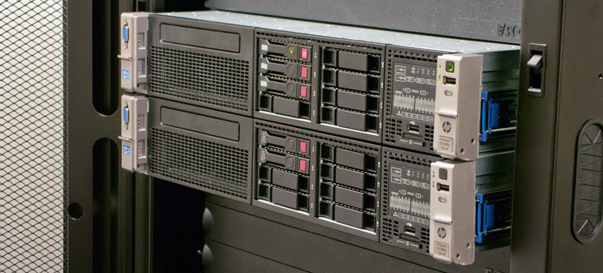

While some may wonder about the relevancy of reviewing servers on a storage website, it's important to realize how vital the compute platform is to storage performance, both directly and indirectly. When testing the latest PCIe Application Accelerators for example, for maximum throughput, it's critical to make sure compute servers are ready in areas ranging from hardware compatibility, performance scaling and saturation, to even often overlooked elements like how a server manages cooling.

Case in point, most 2U servers use riser boards for PCIe expansion, and knowing what drives those slots is just as important as the slots themselves. If one 16-lane PCIe slot is being shared for three slots, those may under-perform compared to a solution that uses two 16-lane PCIe slots to share between three riser slots. We also have an eye toward how well manufacturers make use of the cramped real-estate inside 1U and 2U servers, as all are not created equal. Items in this category can vary from everything from cable management to how many features are integrated versus requiring add-on cards, leaving PCIe expansion entirely open to the end-user instead of utilizing those slots for RAID cards or additional LAN NICs. Even the way server vendors handle the traditional SATA/SAS bays can be vastly different which could be the difference between an ideal server/storage relationship and one that is less desirable.

The HP ProLiant DL380p Gen8 Server series is comprised of 2U, 2-socket compute servers that feature a Smart Array P420i RAID controller with up to 2GB Flash Backed Write Cache (FBWC), up to five PCIe 3.0 expansion slots and one PCIe 2.0 expansion slot, and extensive built-in management capabilities. Our server accepts small form factor (SFF) 2.5-inch SAS, SATA, or SSD drives, while other configurations of the ProLiant DL380p Gen8 servers accepting large form factor (LFF) 3.5-inch drives are also available.

Our HP ProLiant DL380p Gen8 Specifications:
  • Intel Xeon E5-2640 (6 core, 2.50 GHz, 15MB, 95W)
  • Windows Server 2008 R2 SP1 64-Bit
  • Intel C600 Chipset
  • Memory - 64GB (8 x 8GB) 1333Mhz DDR3 Registered RDIMMs
    • 768 GB (24 DIMMs x 32G 2R) Max
  • PCI-Express Slots
    • 1 x PCIe 3.0 x16
    • 1 x PCIe 3.0 x8
    • 1 x PCIe 2.0 x8 (x4 electric)
  • Ethernet - 1Gb 331FLR Ethernet Adapter 4 Ports
  • Boot Drive - 600GB 10,000RPM SAS x 2 (RAID1)
  • Storage Bays - 8 x 2.5" SAS/SATA hot swap
    • Smart Array P420i Controller
  • I/O Ports
    • 7 x USB 2.0 (2 front, 4 rear and 1 internal)
    • 2 x VGA connector (front/rear)
    • Internal SD-Card slot
  • Management
    • HP Insight Control Environment
    • HP iLO 4; hardware-based power capping
  • Form Factor - 2P/2U Rack
  • Power
    • 460W Common Slot Platinum Hot Plug
  • HP Standard Limited Warranty - 3 Years Parts and on-site Labor, Next Business Day
  • Full HP ProLiant DL380p Specifications
Hardware Options

The DL380p Gen8 series features configurations with up to two Intel Xeon E5-2600 family processors, up to five PCI-Express 3.0 expansion slots and one PCI-Express 2.0 slot (three with single CPU, six with dual CPU). The standard riser configuration per CPU includes one x16 PCIe 3.0 slot, one x8 PCIe 3.0 slot, and one x8 PCIe 2.0 slot. HP offers different configuration options, with an optional riser that supports two x16 PCIe 3.0 slots. The unit can also support up to two 150W single-width graphics cards in a two processor, two riser configuration with an additional power feed.


Each Intel Xeon E5-2600 processor socket contains four memory channels that support three DIMMs each for a total of 12 DIMMs per installed processor or a grand total of 24 DIMMs per server. ProLiant DL380p Gen8 supports HP SmartMemory RDIMMs, UDIMMs, and LRDIMMs up to 128GB capacity at 1600MHz or 768GB maximum capacity.


HP FlexibleLOM provides bandwidth options (1G and 10G) and network fabric (Ethernet, FCoE, InfiniBand), with an upgrade path to 20G and 40G when the technology becomes available. HP ProLiant DL380p Gen8 provides a dedicated iLO port and the iLO Management Engine including Intelligent Provisioning, Agentless Management, Active Health System, and embedded Remote Support. This layout allows users to manage the DL380p, without taking over a port from the other four 1GbE offered on-board.

Monitoring and Management

HP Active Health System provides health and configuration logging with HP’s Agentless Management for hardware monitoring and alerts. Automated Energy Optimization analyzes and responds to the ProLiant DL380p Gen8’s array of internal temperature sensors and can signal self-identification location and inventory to HP Insight Control. The HP ProLiant DL380p Gen8 is Energy Star qualified and supports HP's Common Slot power supplies allow for commonality of power supplies across HP solutions. If you configure a ProLiant DL380p Gen8 with HP Platinum Plus common-slot power supplies, the power system can communicate with the company’s Intelligent PDU series to enable redundant supplies to be plugged into redundant power distribution units.
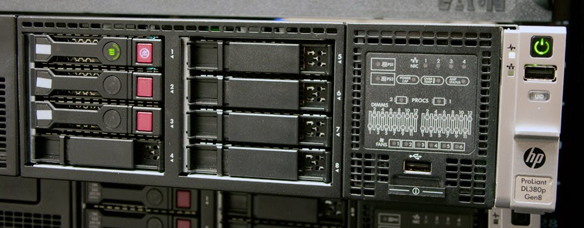

HP also offers three interoperable management solutions for the ProLiant DL380p Gen 8: Insight Control, Matrix Operating Environment, and iLo. HP Insight Control provides infrastructure management to deploy, migrate, monitor, remote control, and optimize infrastructure through a single management console. Versions of Insight Control are available for Linux and Windows central management servers. The HP Matrix Operating Environment (Matrix OE) infrastructure management solution includes automated provisioning, optimization, and recovery management capabilities for HP CloudSystem Matrix, HP’s private cloud and Infrastructure as a Service (IaaS) platform.
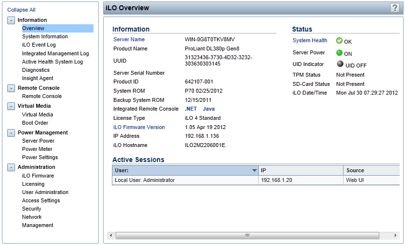

HP iLO management processors virtualize system controls for server setup, health monitoring, power and thermal control, and remote administration. HP iLO functions without additional software installation regardless of the servers' state of operation. Basic system board management functions, diagnostics, and essential Lights-Out functionality ships standard across all HP ProLiant Gen8 rack, tower and blade servers. Advanced functionality, such as graphical remote console, multi-user collaboration, and video record/playback can be activated with optional iLO Advanced or iLO Advanced for BladeSystem licenses.
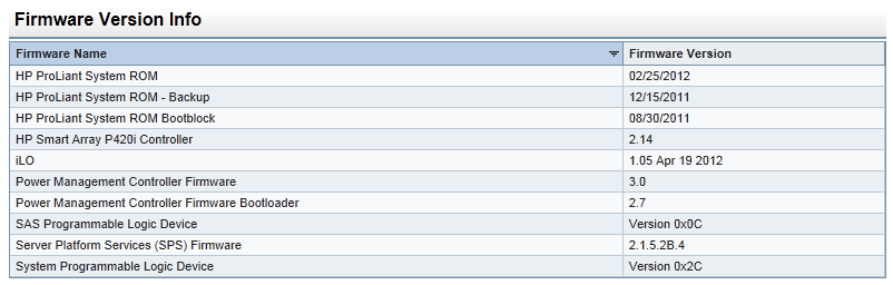

Some of the primary features enabled with advanced iLO functionality include remote console support beyond BIOS access or advanced power monitoring capabilities to see how much power the server is drawing over a given period of time. In our case our system shipped with basic iLO support, which gave us the ability to remotely power on or off the system or provided remote console support (which ended as soon as the OS started to boot). Depending on the installation, many users can probably get by without the advanced features, but when tying the server into large scale-out environments, the advanced iLo featureset can really streamline remote management.

Design and Build

Our DL380p Gen8 review model came with a Sliding-Rack Rail Kit and an ambidextrous Cable Management Arm. The rail kit system offers tool-free installation for racks with square or round mounting holes and features an adjustment range of 24-36 inches and quick release levers. Installation into telco racks requires a third-party option kit. The sliding-rack and cable management arm work together, allowing IT to service the DL380p by sliding it out of the rack without disconnecting any cables from the server. Buyers opting for a more basic approach can still buy the DL380p without rails, or with a basic non-sliding friction mount.
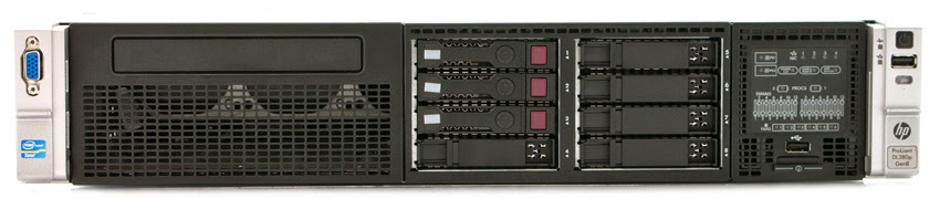

The front of the DL380p features one VGA out and two USB ports. Our unit features eight small form factor (SFF) SAS hot-plug drive bays. There is space for an optional optical drive at to the left of the hot plug bays. With a quick glance of the status LEDs on the front, users can diagnose server failures or make sure everything is running smoothly. If no failures have occurred, the system health LEDs are green. If a failure has occurred, but a redundant feature has enabled the system to continue running, the LED will be amber. If the failure is critical and causes shutdown, the LED illuminates red. If the issue is serviceable without removing the server hood, the External Health LED illuminates. If the hood must be removed, the Internal Health LED illuminates.

The level of detail that HP put into the DL380p is fairly impressive at times, with items as simple as drive trays getting all the bells and whistles. The drive tray includes rotating disk activity LEDs, indicators to tell you when a drive is powered on, and even when not to eject a drive. At times when it seems that all hard drives or SSDs get simple blinking activity LEDs, HP goes the extra mile to provide users with as much information as they can absorb just by looking at the front of the server.
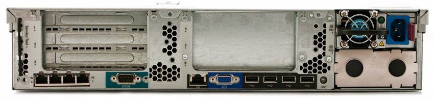

Connectivity is handled from both the front and rear of the DL380p. VGA and USB ports are found on both sides of the server for easy management, although both VGA ports can't be used simultaneously. Additional ports such as a serial interface, and more USB ports can be found on the back of the server along with FlexibleLOM ports (four 1GbE in our configuration) and the iLO LAN connector. To get the ProLiant DL380p Gen8 server up and running immediately, HP ships these servers standard with a 6-foot C-14 to C13 power cord for use with a PDU.
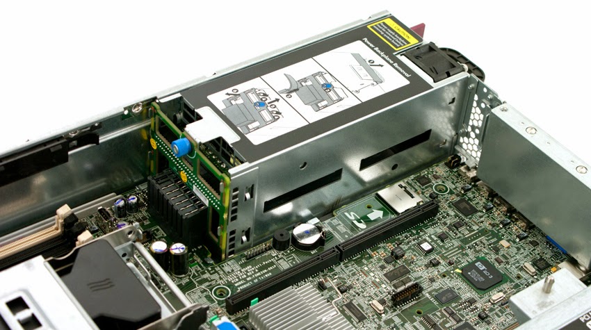

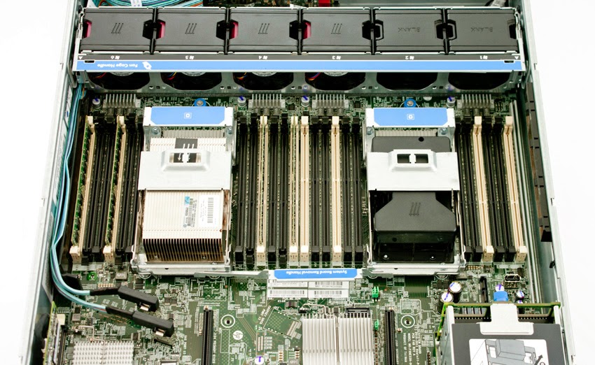
Internally, HP put substantial effort into making the ProLiant DL380p Gen8 easy to service while packing the most features they could into the small 2U form-factor. The first thing buyers will notice is the cabling, or lack thereof, inside the server chassis. Many of the basic features are routed on the motherboard itself, including what tends to be cluttered power cabling. Other tightly-integrated items including the on-board FlexibleLOM 4-port 1GbE NIC and the Smart Array P420i RAID controller, adding network and drive connectivity without taking over any PCIe slots. In a sense this allows buyers to have their cake and eat it too, packing the DL380p with almost every feature and still leaving room for fast PCIe application accelerators or high-speed aftermarket networking interconnects such as 10/40GbE or 56Gb/s InfiniBand.
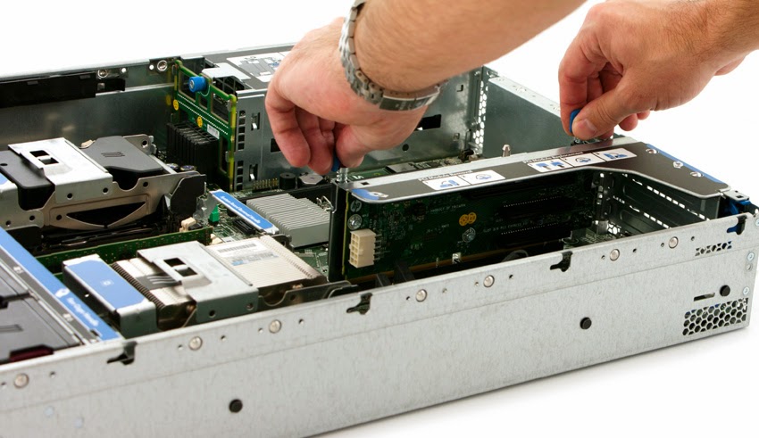

When it comes time to install new hardware or quickly replace faulty buyers or their IT departments will enjoy the tool-free serviceable sections of the DL380p. No matter if you are swapping out system memory, replacing a processor, or even installing a new PCIe add-on card, you don't need to break out a screwdriver. HP also includes a full hardware diagram on the inside of the system cover, making it easy to identify components when it comes time to replacing them.

Cooling

Inside most server chassis, cooling and cable management can go hand in hand. While you can overcome some issues with brute force cooling, a more graceful approach is to remove intrusive cabling that can disrupt proper airflow for efficient and quiet cooling. HP went to great lengths integrating most cables found in servers, including power cabling, or went with flat cables tucked against one side for data connections. You can see this with the on-board Smart Array P420i RAID controller that connects to the front drive bay with flat mini-SAS cables.


While keeping a server cool is just one task to accomplish inside a server, making sure it works and is easily field-serviceable are two distinct items. All fans on the HP DL380p held in with quick-connects, and can be swapped out by removing the top lid in seconds.

On the cooling side of things, the DL380p does a great job of providing dedicated airflow for all the components inside the server chassis, including add-on PCIe solutions. Through the BIOS, users can change the amount of cooling needed, including overriding all automatic cooling options to force max airflow if the need arises. If that's the case, make sure no loose paperwork is around, as it will surely be sucked to the front bezel from the tornado of airflow. In our testing with PCIe Application Accelerators installed and stressed, stock cooling, or slightly increased cooling was enough to keep everything operating smoothly.

Power Efficiency

HP is making a big push into higher efficiency servers that can be seen across the board with a greater push for lower power-draw components. The ProLiant DL380p includes a high-efficiency power supply, our model is equipped with the 94% efficient Common Slot Platinum PSU.


Less power is wasted as heat in the AC to DC conversion process, which means that for every 100 watts you send your power supply, 94 watts reaches the server, instead of 75 watts or less with older models.

Conclusion

We've logged hands on time with just about every major server brand, and even some not so major brands. The one thing that resonates with the HP Gen8 ProLiants is just how tightly they're put together. The interior layouts are clean, cabling is tucked away (or completely integrated with the motherboard) and thoughtfully done and even the PCIe riser boards support the latest generation PCIe storage cards. From a storage perspective, the latter is certainly key, if an enterprise is going to invest in the latest and greatest storage technology, the server better support the expected throughput.

While this first part of our HP ProLiant DL380p review gives a comprehensive overview of the system itself, part two will incorporate performance and compatibility testing with a wide array of storage products. While most SATA and SAS drives will perform roughly the same in any system, the latest PCIe storage solutions have a way of separating the men from the boys in the server world. Stay tuned for our second review installment that will cover these storage concerns and other key areas such as multi-OS performance variability.

Availability

HP ProLiantDL380p Gen8 Servers start $2,569 and are available now.

MSI MS-9A58 Quad LAN Review

MSI IPC launches MS-9A58 industrial system, a compact and fanless embedded IPC powered by an Intel® Atom™ D525 processor with DDR3 support and integrated display interface. It enables much better power savings, while providing top performance and rich I/O capability.


MS-9A58 is powered by the latest Intel® Atom™ D525 dual core processors with DD3 memory up to 4GB for D525. With integrated graphics and memory controllers, these processors deliver graphics core rendering speeds from 200 to 400 MHz while maintaining excellent power efficiency. In addition to higher speeds and less power consumption. The Intel® GMA 3150 graphics engine is built into the chipset to provide fast graphics performance, high visual quality, and flexible display options without the need for a separate graphics card. With a compact mini-ITX system size, system developers get the freedom to design small embedded applications.


MS-9A58 supports 4 Intel 82574L Gb LAN Ports, including one pair of single latch support auto-bypass function. For the storage application, it supports 2 SATA ports. To satisfy increasing demands of connecting more peripheral devices, MS-9A58 is equipped with abundant I/O design, includes one RS-232 and one RS-232/422/485 serial ports with auto-flow control, two COM ports and 6 USB 2.0 ports. Expansion capabilities include two PCI slots, one PCIex1 slot and one mini-PCIe slot. For the internet demand, MS-9A58 comes with a module that has a built-in WiFi 802.11b/g/n module function. MS-9A58 supports ATX and wide range DC 12V / 19V / 24V inputs as the different BOM option.


Key Features:
1. Intel® Pineview D525 Dual Core CPU
2. DDR3 SoDIMM for better memory supply
3. 2 SATA Ports for Storage Application
4. 4 Intel 82574L Gb LAN Ports, including one pair of single latch support auto-bypass function
5. Built-in WiFi 802.11b/g/n module function
6. Wide Range Voltage Input for DC Sku (12/19/24V)
7. Support DirectX10, Shadier Model 4.0 and Intel® Clear Video Technology

With a compact mini-ITX size, MS-9A58 is designed with rich I/O functionality and has the new levels of performance and graphics for the demand in network security applications, such as small business VPN (Virtual Private Network ), VoIP (Voice over Internet Protocol ), SAN (Storage Area Network) and NAS (Network Attached Storage).

The MSI MS-9A58 Quad LAN is really best for embedded system like OpenWrt, pfSense, MonoWall, SmoothWall, DD-Wrt, ZeroShell not to mention other Linux network security OS. Home file server is also applicable such as FreeNAS and SimplyNAS.

CCBoot 3.0 : Server Hardware Requirements

Here is the recommended server hardware for diskless boot with CCBoot.

1.] CPU: Intel or AMD Processor 4 Core or more.
2.] Motherboard: Server motherboard that supports 8GB or more RAM, 6 or more SATA Ports.
3.] RAM: 8GB DDR3 or more.
4.] Hard Disk:At first, we introduce some items.
Image disk: the hard disk that stores the client OS boot data. We call it as "image".
Game disk: the hard disks that store the game data.
Writeback disk: the hard disks that store the client write data. In diskless booting, all data are read and wrote from server. So we need writeback disk to save the client's write data. Other products are also named it as "write cache".

1) One SATA HDD is used for server OS (C:\) and image disk(D:\); some users put image file into SSD disk. It's not necessary. We have RAM cache for image. All image data will be loaded from RAM cache at last. So put image file into SSD disk is not necessary.

2) Two SATA HDD are set up on RAID0 for Game Disk.
We recommend to use Win2008 disk manager to setup RAID0 instead of hardware RAID in BIOS. We recommend to set SATA mode as AHCI in BIOS. Because AHCI is better for writeback disks' write performance. For more information, please refer to AHCI on wiki. In the BIOS, SATA mode can only be one of AHCI and RAID. If we set it as AHCI, the RAID function of the motherboard will be invalid. So we use Win2008 disk manager to setup RAID0. The performance is same as hardware RAID0. Note: If you skip RAID0, the read speed of the game may become slow. But if the clients are less than 50 with SSD cache, it is OK to skip RAID0.

3) One SSD disk for SSD cache. (120G+)

4) Two SATA/SAS/SSD HDD is used for client write-back disk. We do NOT recommend to use RAID for write-back disks. If one disk is broken, we can use the other one. If using RAID for writeback disk, one disk broken will cause all clients stop. On the other hand, CCBoot can do balance for writeback disk. Two disks write performance is better than one RAID disk. Using SSD as writeback disk is better than SATA. SSD has good IOPS. The street said the writing activities are harmful for the lifetime of SSD. In our experience, one SSD for writeback disk can be used for three years at least. It's enough and worth.

Conclusion: You need to prepare 6 HDDs for the server normally. They are 5 SATA HDDs and 1 SSD HDD. 1 SATA for system OS, 2 SATA for game disks, 2 SATA for writeback disks and 1 SSD for cache.

For 25 - 30 client PCs, server should have 8G DDR3 RAM and two writeback disks.
For 30 - 70 client PCs, server should have 16G DDR3 RAM and two writeback disks.
For 70 - 100 client PCs, server should have 32G DDR3 RAM and two writeback disks.
For 100+ client PCs, we recommend to use 2 or more Servers with load balance.
Network: 1000Mb Ethernet or 2 * 1000 Mb Ethernet team network. We recommend Intel and Realtek 1000M Series.

FreeNAS : How-To Setup Home File Server For Free

I download a lot of music. My wife takes a lot of digital photos. My kids also like to save music and photos. Between all of us, we have a lot of media that quickly accumulates on our home PCs. The task of sharing this media between us is a challenge. My wife didn't know how to burn data CDs and my kids didn't have a CD burner. What we needed was a home file server: A dedicated computer used storage and sharing of our files. My research found a ton of products available that would do the job. There are several dedicated Network Attached Storage (NAS) devices that I could purchase, but even the cheapest ones are still several hundred US dollars. Then there is the server software to consider. Microsoft has its Windows Storage Server software that is also several hundred US dollars. There is also many different Linux solutions that require a working knowledge of the linux file system and command line.


In the end I settled on a free product called FreeNAS. As the title suggests, FreeNAS is free network attached storage software, but that is not all. It also has numerous features that make it extremely easy to set up, manage and expand. Plus it has features that allow you to use it as a media server for various devices. Since its hardware requirement is very minimal, this seemed like an ideal product for me to use. With FreeNAS, I was able to use my old desktop PC (a Pentium 4 with 256 MB RAM), as my file server.

Installation and setup:

To set up FreeNAS as a home file server, you must make sure you have all the proper hardware first. This means you need a multiple port router, or switch to connect your file server to as well as a network cable for the server. For the actual server, you will need a PC with at least one hard drive (I started with 2) and a CD-ROM drive.

The setup process was very easy. I downloaded the FreeNAS ISO file and created a Live CD which I inserted into my old PC. If I wanted to, I could have started using it as a file server right there (by simply changing the IP address of the server), but I wanted something that I could use in the long term... something that could auto restart with no user intervention in the event of a power failure. This meant installing it to the hard drive. FreeNAS setup made this easy to do. I simply selected which hard drive to install to, and that was it. After a reboot, I had to set up the network interface. FreeNAS auto-detects which network adapter you have, so selecting it was simple. Next I had to assign an IP address. FreeNAS setup has a default address you can use if you want, but it may not work on your home network. Its best to find out your workstation's IP address (typically assigned by your ISP through DHCP) and set up your FreeNAS server on a similar address. Once this is done, you are pretty much done with working directly with that machine and can now access all your other options through the web interface, which I found very easy to use.

Setting up file shares:

This is probably the most challenging part of the entire setup, but it was still relatively easy to do. Setting up the server to share files is done in 4 steps: Adding a drive, formatting the drive, adding a mount point, then setting up the share. At first the task was a bit daunting, but after grasping the basic concept, it was really quite straight forward. When I added 2 more hard drives to my server, it was simple to configure them for file sharing and within 15 minutes, I had easily tripled my file server storage capacity.

Additional Features:

Even though storage is its primary feature, there is much more that really makes this product shine. It has the ability to support multiple network protocols, including AppleTalk, NFS, FTP, Unison, and iSCSI. It also comes bundled with many extra services like the Transmission Bittorent client, a UPnP server, iTunes server and a basic web server. This means that it is capable of more than just storage. It can be used as part of your home entertainment setup, serving your media to your Home Theater PC, PSP, iPod, or other network devices.

Conclusion:

I'm happy to say that FreeNAS does a great job storing and sharing my files. Since my initial installation of the product, I added and updated 3 hard drives on my server and the process was very easy and straight forward. FreeNAS easily recognized my new hard drives and allowed me to add and share them for storage with no problems. I use the Transmission Bittorrent client to download my media, so I am not tying up my workstation with a separate bit torrent client. If I decide later to add a Linux PC to my home network, I can simply enable the appropriate protocol on my server and have instant access to all my files. Ultimately my goal is to build a home theater PC, so when that is ready, I will already have the media server ready to serve up my media.

I heartily recommend FreeNAS if you are looking for a free (or very inexpensive) solution for a file server. You will need to know some basic technical information about your home network, like your IP address setup, and you will need to have a multiple port router or switch on your home network, but beyond that, it is relatively easy to manage and expand.

Resources:

Website: http://www.freenas.org/
Download: http://sourceforge.net/projects/freenas/files/
Installation instructions: http://www.installationwiki.org/Installing_FreeNAS
FreeNAS Blog: http://blog.freenas.org/
FreeNAS Knowledgebase: http://www.freenaskb.info/kb/
FreeNAS Support Forum: http://sourceforge.net/apps/phpbb/freenas/index.php

Yet Another AoE vs. iSCSI Opinion

That’s right, folks! Yet another asshole blogger here, sharing his AoE (ATA over Ethernet) vs. iSCSI (Internet SCSI) opinion with the world!

As if there wasn’t already enough discussion surrounding AoE vs. iSCSI in mailing lists, forums and blogs, I am going to add more baseless opinion to the existing overwhelming heap of information on the subject. I’m sure this will be lost in the noise but after having implemented AoE with CORAID devices and iSCSI with an IBM (well, LSI) device and iSCSI with software targets in the past I feel I finally have something share.

This isn’t a technical analysis. I’m not dissecting the protocols nor am I suggesting implementation of either protocol for your project. What I am doing is sharing some of my experiences and observations simply because I can. Read on, brave souls.

Background

My experiences with AoE and iSCSI are limited to fairly small implementations by most standards. Multi-terabyte and mostly file serving with a little bit of database thrown in there for good measure. The reasoning behind all the AoE and iSCSI implementations I’ve setup is basically to detach storage from physical servers to achieve:
  1. Independently managed storage that can grow without pain
  2. High availability services front-end (multiple servers connecting to the same storage device(s))
There are plenty of other uses for these technologies (and other technologies that may satisfy these requirement), but that’s where I draw my experiences from. I’ve not deployed iSCSI or AoE for virtual infrastructure which does seem to be a pretty hot topic these days, so if that’s what you’re doing, your mileage will vary.

Performance

Yeah, yeah, yeah, everyone wants the performance numbers. Well, I don’t have them. You can find people comparing AoE and iSCSI performance elsewhere (even if many of the tests are flawed). Any performance numbers I may accidentally provide while typing this up in a mad frenzy are entirely subjective and circumstantial… I may not even end up providing any! Do you own testing, it’s the only way you’ll ever be sure.

The Argument For or Against

I don’t really want to be trying to convince anyone to use a certain technology here. However, I will say it: I lean towards AoE for the types of implementations I mentioned above. Why? One reason: SIMPLICITY. Remember the old KISS adage? Well, kiss me AoE because you’ve got the goods!

iSCSI has the balls to do a lot, for a lot of different situations. iSCSI is routable in layer 3 by nature. AoE is not. iSCSI has a behemoth sized load of options and settings that can be tweaked for any particular implementation needs. iSCSI has big vendor backing in both the target and the initiator markets. Need to export an iSCSI device across a WAN link? Sure, you can do it, never mind that the performance might be less than optimal but the point is it’s not terribly involved or “special” to route iSCSI over a WAN because iSCSI is designed from the get-go to run over the Internet. While AoE over a WAN has been demonstrated with GRE, it’s not inherent to the design of AoE and never will be.

So what does AoE have that iSCSI doesn’t? Simplicity and less overhead. AoE doesn’t have myriad of configuration options to get wrong, it’s really so straight forward that it’s hard to get it wrong. iSCSi is easy to get wrong. Tune your HBA firmware settings or software initiator incorrectly (and the factory defaults can easily be “wrong” for any particular implementation) and watch all hell be unleashed before your eyes. If you’ve ever looked at the firmware options provided to by QLogic in their HBAs and you’re not an iSCSI expert, you’ll know what I’m talking about.

Simplicity Example: Multipath I/O

A great example of AoE’s simplicity vs. iSCSI is when it comes to multipath I/O. Multipath I/O is defined as utilizing multiple paths to the same device/LUN/whatever to gain performance and/or redundancy. This is generally implemented with multiple HBAs or NICs on the initiator side and multiple target interfaces on the target side.

With iSCSI, every path to the same device provides the operating system with a separate device. In Linux, that’ll be /dev/sdd, /dev/sde, /dev/sdf, etc. A software layer (MPIO) is required to manage I/O across all the devices in an organized and sensible fashion.

While I’m a fairly big fan of the latest device-mapper-multipath MPIO layer in modern Linux variants, I find AoE’s multipath I/O method much, much better for the task of providing multiple paths to a storage device because it has incredibly low overhead to setup and manage. AoE’s implementation has the advantage that it doesn’t need to be everything to every storage subsystem, which fortunately or unfortunately device-mapper-multipath has to be.

The AoE Linux driver totally abstracts multiple paths in a way that iSCSI does not by handling all the multipath stuff internally. The host is only provided with a single device in /dev that is managed identically to any other non-multipath device. You don’t even need to configure the driver in any special way, just plug in the interfaces and go! That’s a long shot from what is necessary with MPIO layers and iSCSI.

There’s nothing wrong about device-mapper-multipath and it is quite flexible, but it certainly doesn’t have the simplicity of AoE’s multipath design.

Enterprise Support

Enterprise support is where iSCSI shines in this comparison. Show me a major storage vendor that doesn’t have at least one iSCSI device, even if they are just rebranded. Ok, maybe there are a few vendors out there without an iSCSI solution but for the most part all the big boys are flaunting some kind of iSCSI solution. NetApp, EMC, Dell, IBM, HDS and HP all have iSCSI solutions. On the other hand, AoE only has only a single visible company backing it at the commercial level: CORAID, a spin-off company started by Brantley Coile (yeah, the guy who invented the now-Cisco PIX and AoE). I’m starting to see some Asian manufacturers backing AoE on the hardware level but when it comes to your organization buying rack mount AoE compatible disk trays, CORAID is the only vendor I would suggest at this time.

This isn’t so fantastic for getting AoE into businesses but it’s a start. With AoE in the Linux kernel and Asian vendors packing AoE into chips things will likely pickup for AoE from an enterprise support point of view: It’s cheap, it’s simple and performance is good.

Conclusion

AoE rocks! iSCSI is pretty cool too, but I’ve certainly undergone much worse pain working with much more expensive iSCSI SAN devices vs the CORAID devices. And no performance benefit that I could realize with moderate to heavy file serving and light database workloads. I like AoE over iSCSI but there are plenty of reasons not to like it as well.

ATA-over-Ethernet vs iSCSI

Every so often someone voices interest in ATAoE support for Solaris or tries to engage in an ATAoE versus iSCSI discussion. There isn't much out there in the way of information on the topic so I'll add some to the pot...

If you look just at the names of these two technologies you can easily start to equate them in your mind and start a running mental dialog reguarding which is better. But, most folks make a very common mistake.. ATA-over-Ethernet is exactly that, over ethernet. Whereas iSCSI is Internet SCSI, or as some people prefer to think SCSI over IP. So we've got two differentiators just given the names of these technologies alone: ATA vs SCSI command set, and Ethernet vs IP stack. The interesting thing is the latter discussion.

There is a natural give and take here. The advantage of ATAoE is that you don't have the overhead of translating ATA to SCSI then back to ATA if your using ATA drives, so there is a performance pickup there. Furthermore, because we don't have the girth fo the TCP/IP stack underneight we don't burden the system with all that processing, which adds even more performance. In this sense, ATAoE strips away all the stuff that gets in the way of fast storage over ethernet. But, naturally, there is a catch. You can't route ethernet, thats what TCP/IP is for. That means that with ATAoE your going to be building very small and localized storage networks on a single segment. Think of a boot server which operates without TCP/IP, you've got to have one per subnet so that it see's the requests.

iSCSI on the otherhand might be burdened by the bulk of the TCP/IP stack, however it has the ability to span the internet because of it. You can have an iSCSI target (server) in New York and an iSCSI initiator (client) in London connected across a VPN and its not a problem. Plus, iSCSI is an open and accepted standard. ATAoE on the otherhand is open but it was created and developed by Coraid who also happens to be the only supplier of ATAoE enclosures. That may change, but we'll see how well it catches on.

ATAoE promises to be smaller and faster than the industry standard iSCSI, and it is, but unless you are using a very local application your going to be in trouble. Not to mention the lack of enclosure and driver support for non-Linux systems.

The question then becomes: Should OpenSolaris support ATAoE? Personally, I don't think we should ever be against the idea of anything new, if someone wants to do it, we should all get behind it. But looking at Solaris I doubt the idea would stick. First and foremost Solaris is an OS that adheres to the standards and plays by the rules, even when its painful. Linux doesn't always play by those rules and often it gains from breaking them. Linux is a great experimental platform, no doubt, but I just don't think the ideals of ATAoE mesh well with the goals of Solaris. Furthermore, ATAoE doesn't offer the level of scalability, flexablilty, and managability that we get with iSCSI. The performance hit of TCP/IP is definately a downside, but the advantages it brings to the table far out weight the downsides I think.

Here are some links to help you explore the subject more on your own:

ATA over Ethernet a ‘strict no’ in Data Center Networks

While exploring for storage networking technologies, there are chances that one can come across ATA over Ethernet (ATAoE). It is nothing but, ATA command set transported directly within Ethernet Frames. ATA over Ethernet approach is similar to that of a Fibre Channel over Ethernet (FCoE), but in reality the former has gained fewer acceptances from the industry.

As a matter of fact, ATAoE is limited to a single vendor (Vendor lock-in) and its specifications reveal that its protocol length is limited to 12 pages when compared with iSCSI, which has a 257 pages length of protocol.

Although, ATA over Ethernet was considered as an unsighted fast technology, it got overshadowed by the virtues of the iSCSI in the long run.

Storage networking specialists go with the opinion that ATAoE protocol is broken and so it is not a good recommendation to be deployed in the data centers. In order to further cement this statement, let us go into further details.
  • ATA over Ethernet has no sequencing- This protocol doesn’t support single sequence of numbers, which allow the storage arrays and servers to differentiate between requests or split a single request into numerous Ethernet frames. As a result of no sequencing, ATAoE offers its server the facility to go for a single request with a particular storage array.
  • ATAoE offers zero transmission- This protocol has no packet loss detection or recovery mechanism.
  • No fragmentation- ATA over Ethernet requests fit directly into Ethernet frames and so the fragmentation of a single request into multiple frames is not possible. As a result the achievement of data flow is almost zero. With the use of jumbo frames, the transfer of only two sectors is possible via each request.
  • Authentication is nil- This protocol if proposed for use in data centers, will not have authentication. So, as a result there is no network security in this protocol and so non-routability of AoE is a source of inherent security.
  • Asynchronous writes have weak support- Due to the absence of retransmissions and sequencing, asynchronous writes are handled in an in-considerate fashion.
The final word is that this protocol would have worked almost 30 years ago, when TFTP-Trivial file transfer protocol was designed. But now, in the present world, it will simply be treated as a broken protocol design class.

According to analysis of industry specialists, just go on with an ATAoE protocol to build a home network. For mission critical data center applications, ATA over Ethernet is a ‘strict no’.

Dec 11, 2014

Understanding ADSL Technology

An acronym for Asymmetric Digital Subscriber Line, ADSL is the technology that allows high-speed data to be sent over existing POTS (Plain Old Telephone Service) twisted-pair copper telephone lines. It provides a continuously available data connection whilst simultaneously providing a continuously available voice-grade telephony circuit on the same pair of wires.

ADSL technology was specifically designed to exploit the "one-way" nature of most internet communications where large amounts of data flow downstream towards the user and only a comparatively small amount of control/request data is sent by the user upstream. As an example, MPEG movies require 1.5 or 3.0 Mbps down stream but need only between 16kbps and 64kbps upstream. The protocols controlling Internet or LAN access require somewhat higher upstream rates but in most cases can get by with a 10 to 1 ratio of downstream to upstream bandwidth. The ADSL specification supports data rates of 0.8 to 3.5 Mbit/s when sending data (the upstream rate) and 1.5 to 24 Mbit/s when receiving data (the downstream rate). The different upstream and downstream speeds is the reason for including "asymmetric" in the technology's name.

ADSL Standard Common Name Downstream rate Upstream rate
ANSI T1.413-1998 Issue 2
ADSL
8 Mbit/s
1.0 Mbit/s
ITU G.992.1
ADSL (G.DMT)
8 Mbit/s
1.0 Mbit/s
ITU G.992.1 Annex A
ADSL over POTS
8 Mbit/s
1.0 MBit/s
ITU G.992.1 Annex B
ADSL over ISDN
8 Mbit/s
1.0 MBit/s
ITU G.992.2
ADSL Lite G.Lite)
1.5 Mbit/s
0.5 Mbit/s
ITU G.992.3/4
ADSL2
12 Mbit/s
1.0 Mbit/s
ITU G.992.3/4 Annex J
ADSL2
12 Mbit/s
3.5 Mbit/s
ITU G.992.3/4 Annex L
RE-ADSL2
5 Mbit/s
0.8 Mbit/s
ITU G.992.5
ADSL2+
24 Mbit/s
1.0 Mbit/s
ITU G.992.5 Annex L
RE-ADSL2+
24 Mbit/s
1.0 Mbit/s
ITU G.992.5 Annex M
ADSL2+
24 Mbit/s
3.5 Mbit/s

The downstream and upstream rates displayed in the above table are theoretical maximums. The actual data rates achieved in practice depend on the distance between the DSLAM (in the telephone exchange) and the customer's premises, the gauge of the POTS cabling and the presence of induced noise or interference.

Broadband is generally defined as a connection which is greater than 128kbs (kilo-bits per second).

Voice-grade telephony uses a bandwidth of 300Hz to 3.4kHz. The sub 300Hz bandwidth can be used for alarm-system data-transfer/monitoring. Bandwidth above 3.4kHz can be used to carry ADSL traffic.

Analogue voice circuits have a nominal 600 ohms impedance at the VF frequency range but exhibit an impedance of around 100 ohms at the frequency range used by ADSL.

DMT Discrete MultiTone modulation technology is used to superimpose the ADSL bandwidth on top of the telephony bandwidth.ADSL typically uses frequencies between 25 kHz and around 1.1 MHz. The lower part of the ADSL spectrum is for upstream tansmission (from the customer) and the upper part of the spectrum is for downstream (towards the customer) transmission.

The ADSL standard allows for several spectra divisions but the upstream band is typically from 25 to 200 kHz and the downstream band is typically 200kHz to 1.1MHz. in a FDM Frequency Division Multiplexed system, different frequency ranges are used for upstream and downstream traffic. Echo-cancelled ADSL allows the downstream band to overlap the upstream band, significantly extending the available downstream bandwidth and extends the upstream bandwidth to provide faster upstream data rates.

POTS/ADSL spectrum allocation is represented in the following diagram.


A DSLAM Digital Subscriber Line Access Multiplexer is installed at the telephone exchange. and has a modem for each customer and network interface equipment. A POTs Splitter Rack is used to separate voice traffic and data traffic on the customers telephone line.

ADSL filters and filter/splitters are used in the customer's premises to separate ADSL data from analogue speech signals and prevent interference between the two types of service. It's important that the specifications of the filters and filter/splitter you use are checked to ensure that effective filtering and equipment isolation and protection are achieved.

The ADSL standard (G.99x.x series) covers several xDSL systems, protocols and tests. They encompass a framework for operation with individual networks and providers free to adapt their system within the framework guidelines. The standards provide the boundaries for equipment manufacturers.

ADSL Physical (PHY) Layer Parameters

Downstream
Overall symbol rate 4kHz
Number of carriers per DMT symbol 256
Subcarrier spacing 4.3125kHz
Cyclic prefix length 32 samples
Operational modes FDM or Echo Cancelled
FDM Mode frequency range 64 to 1100kHz
Echo Cancelled Mode frequency range 13 to 1100kHz
Number of bits assigned per subcarrier 0 to 15 (no bits assigned to 64k QAM)*
Synchronisation Pilot tone at subcarrier 64, f = 276kHz
Upstream
Number of subcarriers per DMT symbol 32
Cyclic prefix length 4 samples
FDM Mode frequency range 11 to 43 kHz
Echo Cancelled Mode frequency range 11 to 275 kHz
Synchronisation Pilot Tone at subcarrier 16, f = 69kHz
Handshake/initialisation Per G.994.1

* The lower three to six subcarriers are set to a gain of "0" (turned off) to permit the simultaneous operation of a POTS service provided that a filter/splitter is installed at the customer's premises telephone line entry point.

pcbuzzcenter : Diskless iCafe LANshop

Brand New PC Buzz Internet Cafe (AMD) *Diskless* 30 Units -1 Timer - 1 Server
Brand new with factory warranty
Price: factory price
Location: Quezon City
The current setup is enough to run the latest games at modest settings.
We only provide top quality brands and models suited for Internet Cafe and Lanshops.
Gskill 1600 RAMs are well suited to improve gaming performance.
Spec:
Client Specifications: (30 Units)
AMD Trinity A6-5400K Processor
4GB Gskill Ripjaws X DDR3-1600 RAM
Gigabyte F2A55M DS2 Motherboard
18.5 LED Philips or AOC Monitor
Core Elite Casing w/ 600 Watts PSU
Genius Keyboard and Mouse Combo PS2
Soncm Headset w/ Mic
Timer Specifications: (1 Unit)
AMD Trinity A6-5400K Processor
4GB Gskill Ripjaws X DDR3-1600 RAM
Gigabyte F2A55M DS2 Motherboard
18.5 LED Philips or AOC Monitor
Western Digital 500GB SATA 3.0 HDD
Core Elite Casing w/ 600 Watts PSU
HP DVD-RW Drive
Genius Keyboard and Mouse Combo PS2
Fortress USB Speakers
Server Specifications: (1 Unit)
AMD Trinity A8-5600K Processor
16GB Gskill Ripjaws X DDR3-1600 Dual Channel RAM
Gigabyte F2A55M DS2 Motherboard
ADATA or Crucial 128GB SSD (Server / Client OS)
Western Digital 1TB Black SATA (Game Disk)
ADATA or Crucial 128GB SSD (Write Back)
Aerocool VS3 Casing
Corsair VS 550 Watts PSU
Genius Keyboard and Mouse Combo PS2
Bosline 650VA UPS
Network:
(2) TP Link 24-Port Gigabit Switch
DLink Original CAT5E Cable 305 Meters *Boxed*
80 Pieces RJ45 *Free*
Optional and Add Ons:
TP-Link 300 Mbps Wireless N Router
Epson L210 (All In One) w/ CISS
(2) Broadcomm Server LAN Card
CC Boot License Only
(Configure Your Own Diskless Setup, Tweakable and Legitimate DisklessProgram)
QQ Diskless Setup and Service
(Network Cable Crimping, Server Imaging, Timer Setup and Overall Client Setup)
ALL parts are top quality branded
ADD on:
Windows 7 license, Antivirus license, Microsoft Office license
We can deliver or you can pick up at our warehouse
We can custom build your PC that is depend on your spec
We can give quotation to your PC spec
For more info you can contact me Nino
Sun 09331998650 call, txt, apps available Viber, Line, Wechat, Tango
Globe 09054992358 call and txt
Smart 09982582976 call and txt
Facebook PC buzz
Email or ym: buzzpc@yahoo.com.ph

WDS Overview : Wireless Distribution System

A wireless distribution system (WDS) is a system enabling the wireless interconnection of access points in an IEEE 802.11 network. It allows a wireless network to be expanded using multiple access points without the traditional requirement for a wired backbone to link them. The notable advantage of WDS over other solutions is it preserves the MAC addresses of client frames across links between access points.


An access point can be either a main, relay, or remote base station.
  • A main base station is typically connected to the (wired) Ethernet.
  • A relay base station relays data between remote base stations, wireless clients, or other relay stations; to either a main, or another relay base station.
  • A remote base station accepts connections from wireless clients and passes them on to relay stations or to main stations. Connections between "clients" are made using MAC addresses.
All base stations in a wireless distribution system must be configured to use the same radio channel, method of encryption (none, WEP, WPA or WPA2) and the same encryption keys. They may be configured to different service set identifiers. WDS also requires every base station to be configured to forward to others in the system.

WDS may also be considered a repeater mode because it appears to bridge and accept wireless clients at the same time (unlike traditional bridging). However, with the repeater method, throughput is halved for all clients connected wirelessly. This is because wifi is an inherently half duplex medium and therefore any wifi device functioning as a repeater must use the Store and forward method of communication.

WDS may be incompatible between different products (even occasionally from the same vendor) since the IEEE 802.11-1999 standard does not define how to construct any such implementations or how stations interact to arrange for exchanging frames of this format. The IEEE 802.11-1999 standard merely defines the 4-address frame format that makes it possible.

Technical

WDS may provide two modes of access point-to-access point (AP-to-AP) connectivity:
  • Wireless bridging, in which WDS APs (AP-to-AP on sitecom routers AP) communicate only with each other and don't allow wireless stations (STA) (also known as wireless clients) to access them
  • Wireless repeating, in which APs (WDS on sitecom routers) communicate with each other and with wireless STAs
Two disadvantages to using WDS are:
  • The maximum wireless effective throughput may be halved after the first retransmission (hop) being made. For example, in the case of two APs connected via WDS, and communication is made between a computer which is plugged into the Ethernet port of AP A and a laptop which is connected wirelessly to AP B. The throughput is halved, because AP B has to retransmit the information during the communication of the two sides. However, in the case of communications between a computer which is plugged into the Ethernet port of AP A and a computer which is plugged into the Ethernet port of AP B, the throughput is not halved since there is no need to retransmit the information. Dual band/radio APs may avoid this problem, by connecting to clients on one band/radio, and making a WDS network link with the other.
  • Dynamically assigned and rotated encryption keys are usually not supported in a WDS connection. This means that dynamic Wi-Fi Protected Access (WPA) and other dynamic key assignment technology in most cases cannot be used, though WPA using pre-shared keys is possible. This is due to the lack of standardization in this field, which may be resolved with the upcoming 802.11s standard. As a result only static WEP or WPA keys may be used in a WDS connection, including any STAs that associate to a WDS repeating AP.
OpenWRT, a universal third party router firmware, supports WDS with WPA-PSK, WPA2-PSK, WPA-PSK/WPA2-PSK Mixed-Mode encryption modes. Recent Apple base stations allow WDS with WPA, though in some cases firmware updates are required. Firmware for the Renasis SAP36g super access point and most third party firmware for the Linksys WRT54G(S)/GL support AES encryption using WPA2-PSK mixed-mode security, and TKIP encryption using WPA-PSK, while operating in WDS mode. However, this mode may not be compatible with other units running stock or alternate firmware.

Dec 10, 2014

Port Switching using Switch Chip on RouterOS

Switch Chip features are implemented in RouterOS (complete set of features implemented starting from version v4.0).

Command line config is located under /interface ethernet switch menu.
This menu contains a list of all switch chips present in system, and some sub-menus as well.

/interface ethernet switch print
Flags: I - invalid
 #   NAME     TYPE         MIRROR-SOURCE   MIRROR-TARGET
 0   switch1  Atheros-8316 ether2          none

Port Switching
Switching feature allows wire speed traffic passing among a group of ports, like the ports were a regular Ethernet Switch (L2).
This feature can be configured by setting a master-port property to one ore more ports in /interface ethernet menu.
A master-port will be the port through which the RouterOS will communicate to all ports in the group.
Interfaces for which the master-port is specified become inactive – no traffic is received on them and no traffic can be sent out.

For example consider a router with five ethernet interfaces:

/interface ethernet print
Flags: X - disabled, R - running, S - slave
 #    NAME    MTU   MAC-ADDRESS       ARP      MASTER-PORT SWITCH
 0 R  ether1  1500  XX:XX:XX:XX:XX:AB enabled
 1    ether2  1500  XX:XX:XX:XX:XX:AC enabled  none        switch1
 2    ether3  1500  XX:XX:XX:XX:XX:AD enabled  none        switch1
 3    ether4  1500  XX:XX:XX:XX:XX:AE enabled  none        switch1
 4 R  ether5  1500  XX:XX:XX:XX:XX:AF enabled  none        switch1

Configuring a switch containing three ports: ether3, ether4 and ether5.
ether3 is now the master-port of the group.

/interface ethernet set ether4,ether5 master-port=ether3
 
/interface ethernet print
Flags: X - disabled, R - running, S - slave
 #    NAME    MTU   MAC-ADDRESS       ARP      MASTER-PORT SWITCH
 0 R  ether1  1500  XX:XX:XX:XX:XX:AB enabled
 1    ether2  1500  XX:XX:XX:XX:XX:AC enabled  none        switch1
 2 R  ether3  1500  XX:XX:XX:XX:XX:AD enabled  none        switch1
 3  S ether4  1500  XX:XX:XX:XX:XX:AE enabled  ether3      switch1
 4 RS ether5  1500  XX:XX:XX:XX:XX:AF enabled  ether3      switch1

Note: previously a link was detected only on ether5 (R Flag), as the ether3 becomes master-port the running flag is propagated to referring master-port.


A packet received by one of the ports always passes through the switch logic at first. Switch logic decides to which ports the packet should be going to. Passing packet up or giving it to RouterOS is also called sending it to switch chips CPU port.

That means that at the point switch forwards the packet to cpu port the packet starts to get processed by RouterOS as some interfaces incoming packet. While the packet does not have to go to cpu port it is handled entirely by switch logic and does not require any cpu cycles and happen at wire speed for any frame size.

Interface Bonding 802.3ad (LACP) with Mikrotik and Cisco

Bonding (also called port trunking or link aggregation) can be configured quite easily on RouterOS-Based devices.

Having 2 NICs (ether1 and ether2) in each router (Router1 and Router2), it is possible to get maximum data rate between 2 routers, by aggregating port bandwidth.

To add a bonding interface on Router1 and Router2:

/interface bonding add slaves=ether1,ether2

(bonding interface needs a couple of seconds to get connectivity with its peer)

Link Monitoring:
Currently bonding in RouterOS supports two schemes for monitoring a link state of slave devices: MII and ARP monitoring. It is not possible to use both methods at a time due to restrictions in the bonding driver.

ARP Monitoring:
ARP monitoring sends ARP queries and uses the response as an indication that the link is operational. This also gives assurance that traffic is actually flowing over the links. If balance-rr and balance-xor modes are set, then the switch should be configured to evenly distribute packets across all links. Otherwise all replies from the ARP targets will be received on the same link which could cause other links to fail. ARP monitoring is enabled by setting three properties link-monitoring, arp-ip-targets and arp-interval. Meaning of each option is described later in this article. It is possible to specify multiple ARP targets that can be useful in a High Availability setups. If only one target is set, the target itself may go down. Having an additional targets increases the reliability of the ARP monitoring.

MII Monitoring:
MII monitoring monitors only the state of the local interface. In RouterOS it is possible to configure MII monitoring in two ways:

MII Type 1: device driver determines whether link is up or down. If device driver does not support this option then link will appear as always up.
MII Type 2: deprecated calling sequences within the kernel are used to determine if link is up. This method is less efficient but can be used on all devices. This mode should be set only if MII type 1 is not supported.

Main disadvantage is that MII monitoring can’t tell if the link actually can pass the packets or not even if the link is detected as up.

MII monitoring is configured setting desired link-monitoring mode and mii-interval.

Configuration Example: 802.3ad (LACP) with Cisco Catalyst GigabitEthernet Connection.

/inteface bonding add slaves=ether1,ether2 \
   mode=802.3ad lacp-rate=30secs \
   link-monitoring=mii-type1 \
   transmit-hash-policy=layer-2-and-3


Other part configuration (assuming the aggregation switch is a Cisco device, usable in EtherChannel / L3 environment):

!
interface range GigabitEthernet 0/1-2
   channel-protocol lacp
   channel-group 1 mode active
!
interface PortChannel 1
   no switchport
   ip address XXX.XXX.XXX.XXX XXX.XXX.XXX.XXX
!

Or for EtherChannel / L2 environment:

!
interface range GigabitEthernet 0/1-2
   channel-protocol lacp
   channel-group 1 mode active
!
interface PortChannel 1
   switchport
   switchport mode access
   swichport access vlan XX
!